96 Rockwell Automation Publication 2198-UM001D-EN-P - May 2014
Chapter 5 Connecting the Kinetix 5500 Drive System
External Shunt Resistor
Connections
Follow these guidelines when wiring your 2097-Rx shunt resistor:
• Refer to External Shunt Resistor
on page 42 for noise zone considerations.
• Refer to Shunt Resistor Wiring Example
on page 194.
• Refer to the installation instructions provided with your Bulletin 2097
shunt resistor, publication 2097-IN002
.
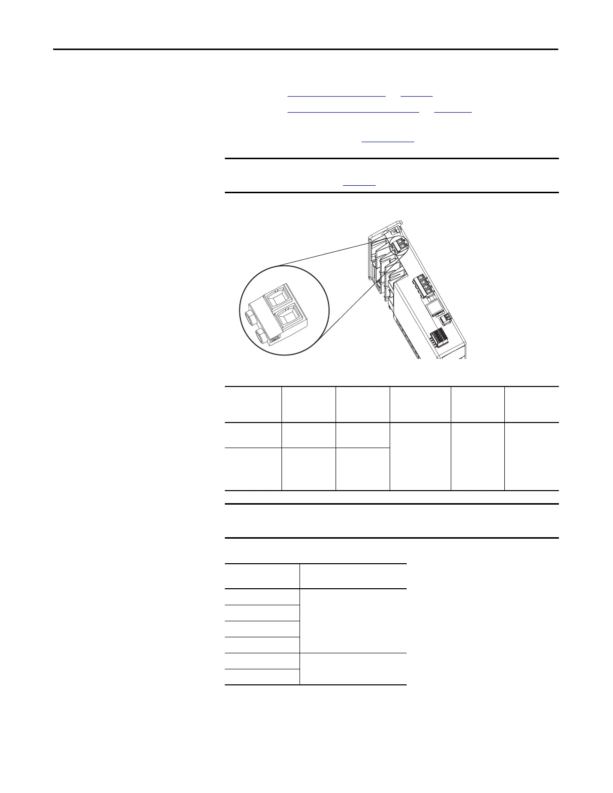
Figure 56 - RC Connector Wiring
Table 49 - Shunt Resistor (RC) Connector Specifications
Table 50 - Shunt Resistor Selection
To improve system performance, run wires and cables in the wireways as
established in Chapter
2.
Kinetix 5500 Drive
Top View
Drive Cat. No. Pin Signal
Recommended
Wire Size
mm
2
(AWG)
Strip Length
mm (in.)
Torque Value
N•m (lb•in)
2198-H003-ERSx
2198-H008-ERSx
RC-1
RC-2
SH
DC+
4…0.5
(12…20)
8.0 (0.31)
0.5…0.6
(4.4…5.3)
2198-H015-ERSx
2198-H025-ERSx
2198-H040-ERSx
2198-H070-ERSx
RC-1
RC-2
DC+
SH
You must disconnect the internal shunt wires at the RC connector before
connecting the Bulletin 2097 shunt resistor wires.
Drive Cat. No.
Bulletin 2097 Shunt Resistor
Cat. No.
2198-H003-ERSx
2097-R7
2198-H008-ERSx
2198-H015-ERSx
2198-H025-ERSx
2198-H040-ERSx
2097-R6
2198-H070-ERSx

 Loading...


