Rockwell Automation Publication 2198-UM001D-EN-P - May 2014 215
Sizing Multi-axis Shared-bus Configurations Appendix C
Table 86 - Shared DC Panel Layout
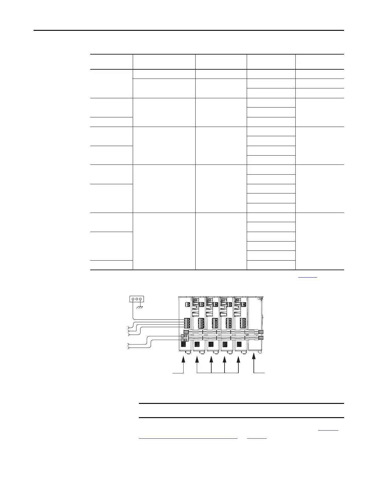
Figure 100 - Typical DC Common Bus Configuration
For an example shared DC installation with additional details, refer to Typical
Shared DC Common-bus Installations on page 18.
Frame Size
Combination
Leader Drive Cat. No. Follower Drives, max
(1)
Follower Cat. No.
Number of Capacitor
Modules, max
1
2198-H003-ERSx 4 2198-H003-ERSx 0
2198-H008-ERSx 4
2198-H003-ERSx 1
2198-H008-ERSx 1
2 and 1
2198-H015-ERSx 6
2198-H003-ERSx
12198-H008-ERSx
2 2198-H015-ERSx
2 and 1
2198-H025-ERSx 6
2198-H003-ERSx
3
2198-H008-ERSx
2
2198-H015-ERSx
2198-H025-ERSx
2 and 1
2198-H040-ERSx 6
2198-H003-ERSx
3
2198-H008-ERSx
2
2198-H015-ERSx
2198-H025-ERSx
2198-H040-ERSx
3 and 1
2198-H070-ERSx 7
2198-H003-ERSx
4
2198-H008-ERSx
3 and 2
2198-H015-ERSx
2198-H025-ERSx
2198-H040-ERSx
3 2198-H070-ERSx
(1) For Bulletin 2198 capacitor module maximum values, refer to the Kinetix 5500 Capacitor Module Installation Instructions, publication 2198-IN004.
Bonded Cabinet
Ground
Three-phase
Input Power
24V Input
Control Power
2198-H040-ERSx
Common-bus Leader Drive
2198-H008-ERSx
Common-bus
Follower Drives
2198-CAPMOD-1300 Capacitor Module
(optional component)
DC Bus Connections
Total number of drives in Kinetix 5500 drive system must not exceed 8.

 Loading...


