94 Rockwell Automation Publication 2198-UM001D-EN-P - May 2014
Chapter 5 Connecting the Kinetix 5500 Drive System
Table 47 - 2090-CFBM7DF-CEAxxx Feedback Cables
A mounting bracket is included with the 2198-H2DCK converter kit to secure
the kit to the drive. Install the mounting bracket in the mounting position
specific to the frame size of your drive.
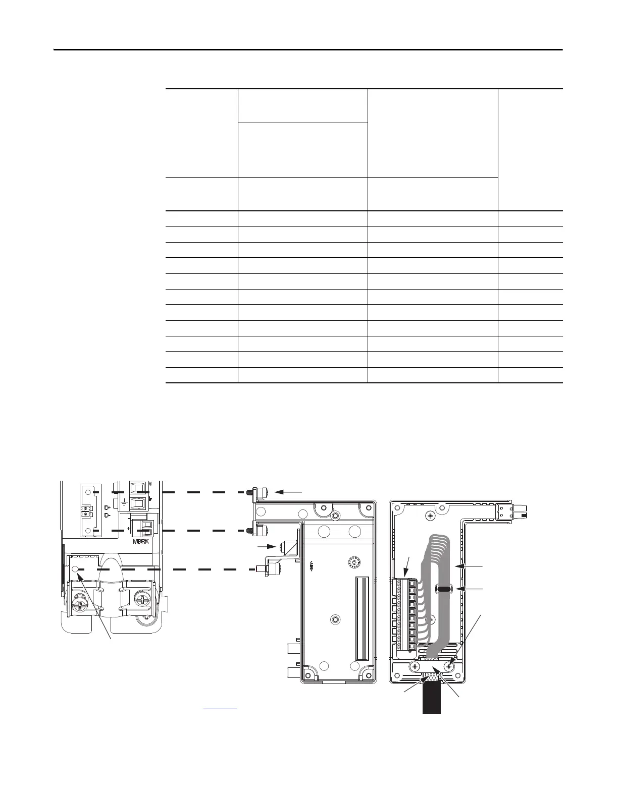
Figure 54 - Wiring the 2198-H2DCK Feedback Converter Kit
Rotary Motors
MPL-B15xxx…MPL-B2xxx-V/Ex4/7xAA
MPF/MPS-Bxxx-M/S
MPF-A5xxx-M/S
MPL-A15xxx…MPL-A2xxx-V/Ex4/7xAA
MPF/MPS-A3xx-M/S
MPF/MPS-A4xx-M/S
MPF/MPS-A45xx-M/S
MPS-A5xxx-M/S
MPL-A3xxx-M/Sx7xAA
MPL-A4xxx-M/Sx7xAA
MPL-A45xxx-M/Sx7xAA
MPM-A115xxx…MPM-A130xxx-M/S
2198-H2DCK
Converter Kit Pin
MPL-B3xxx…MPL-B6xxx-M/Sx7xAA
MPL-A5xxx-M/Sx7xAA
MPM-A165xxx…MPM-A215xxx
MPM-Bxxxxx-M/S
Linear Actuators
MPAS-Bxxxxx-VxxSxA
MPAR-Bxxxx, MPAI-Bxxxx
LDAT-Sxxxxxx-xDx
MPAS-Axxxxx-VxxSxA
MPA
R-Axxxx, MPAI-Axxxx
1Sin+Sin+1
2Sin-Sin-2
3Cos+Cos+3
4Cos-Cos-4
5Data+ Data+ 5
6Data- Data- 10
9Reserved EPWR_5V 14
10 ECOM ECOM 6
(1)
11 EPWR_9V Reserved 7
12 ECOM ECOM 6
13 TS+ TS+ 11
(1) The ECOM and TS- connections are tied together and connect to the cable shield.
Shield Clamp
Clamp Screws (2)
Service Loops
Tie Wrap for Stress Relief
and Wire Management
Mounting Screws (2)
Mounting Bracket
Frame 2 Mounting Position
(catalog numbers 2198-H015-ERSx,
2198-H025-ERS, and 2198-H040-ERSx)
Frame 1 Mounting Position
Frame 3 Mounting Position
(catalog number 2198-H070-ERSx)
(catalog numbers 2198-H003 ERSx
and 2198-H008-ERSx)
Refer to Hiperface to DSL Feedback Converter Kit Installation Instructions,
publication 2198-IN006
, for converter kit specifications.
10-pin
Connector
Converter Kit Mounting Hole
with Protective Cover Removed
(frame 1 drive example shown)
1. Place exposed cable shield
in the channel.
2. Place the shield clamp over
the exposed shield.
3. Tighten screws, torque
0.3 N•m (2.6 lb•in).
Exposed Shield
Aligned
in the Cable Channel

 Loading...


