C-14 Application Notes
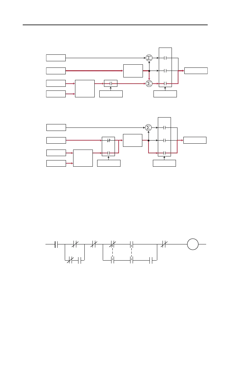
It can operate as trim mode by summing the PI loop output with a master
speed reference.
Or, it can operate as control mode by supplying the entire speed
reference. This method is identified as “exclusive mode”
PI Enable
The output of the PI loop can be turned on (enabled) or turned off
(disabled). This control allows the user to determine when the PI loop is
providing part or all of the commanded speed. The logic for enabling the
PI loop is shown below.
The drive must be running for the PI loop to be enabled. The loop will be
disabled when the drive is ramping to a stop (unless “Stop Mode” is
configured in [PI Configuration]), jogging or the signal loss protection
for the analog input(s) is sensing a loss of signal.
If a digital input has been configured to “PI Enable,” two events are
required to enable the loop: the digital input must be closed AND bit 0 of
the PI Control parameter must be = 1.
+
Spd Cmd
Process PI
Controller
Linear Ramp
& S-Curve
+
+
+
PI Enabled
Speed Control
Spd Ref
PI Ref
PI Fbk
Slip Adder
Open
Loop
Slip
Comp
Process
PI
Spd Cmd
Process PI
Controller
Linear Ramp
& S-Curve
+
+
PI Enabled
Speed Control
Spd Ref
PI Ref
PI Fbk
Slip Adder
Open
Loop
Slip
Comp
Process
PI
Drive
Running
Drive
Ramping
to Stop
Drive
Jogging
Bit 0 of
[PI Control] = 1
(enabled)
[PI Configuration]
Signal Loss
The Configured
Digital Input
is Closed
A Digital Input
is Configured
to PI Enable
"Enabled" Status
Digital Input
is Reflected
in [PI Status]
Bit 0 = 1
The PI Loop
is Enabled
Bit 0 Bit 6
20B-UM001.book Page 14 Thursday, June 20, 2013 1:55 PM

 Loading...


