Application Notes C-15
If no digital input is configured to “PI Enable,” then only the Bit 0 = 1
condition must be met. If the bit is permanently set to a “1”, then the
loop will become enabled as soon as the drive goes into “run”.
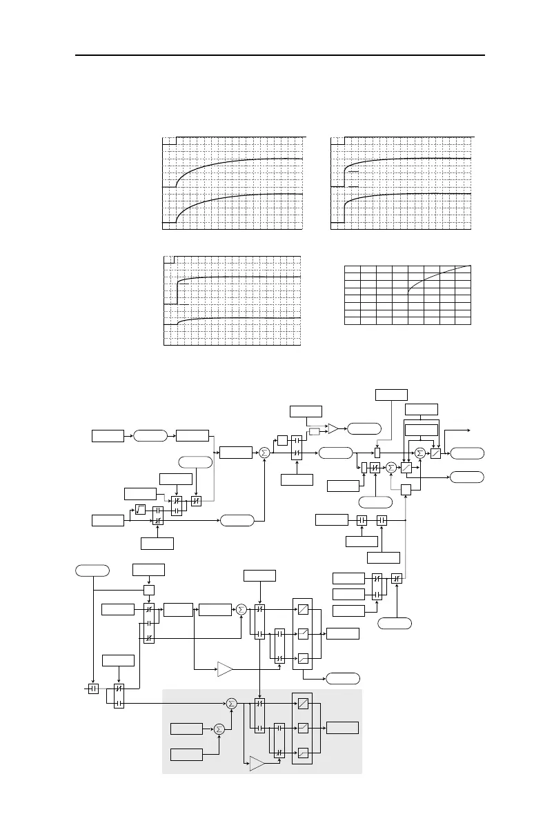
PI Enabled
Spd Cmd
PI Output
PI Pre-load Value
PI Pre-load Value = 0 PI Pre-load Value > 0
Pre-load to Command Speed
PI Enabled
Spd Cmd
PI Output
Start at Spd Cmd
-100.0 -75.0 -50.0 -25.0 0.0 25.0 50.0 75.0 100.0
Normalized Feedback
Normalized SQRT(Feedback)
-100.0
-75.0
-50.0
-25.0
0.0
25.0
50.0
75.0
100.0
+
+
+
+
z
-1
*
*
PI Fbk
PI Error
PI Output
PI Ref
PI Cmd
Linear
Ramp
-
+
-
Linear Ramp
& S-Curve
Spd Ramp
0
+
+
Zclamped
In Limit
PI XS Error
abs
PI_Config
.Exclusive
Current Limit
or Volt Limit
Spd Cmd
*(PI Ref Sel)
*(PI Fbk Sel)
PI Kp
PI Ki
PI Neg Limit
PI Pos Limit
PI_Status
.Hold
Spd Ref
&
PI_Config
.RampCmd
PI_Status
.Enabled
PI_Config
.Invert
PI_Config
.Sqrt
0
PI_Config
.Torq Trim
PI_Config
.SpdReg
PI_Status
.Enabled
PI_Config
.ZeroClamp
PI ExcessErr
PI_Config
.PreloadCmd
Preload Value
PI_Status
.Enabled
Spd Cmd
+32K
0
-32K
0
+32K
-32K
Spd Cmd
to A
A
Torq Ref A
Torq Ref B
0
+800
0
-800
0
+800
-800
+
+
+
+
Torq Cmd
Vector Control Option
20B-UM001.book Page 15 Thursday, June 20, 2013 1:55 PM

 Loading...


