Publication 2098-IN005C-EN-P — March 2008
Interconnect Diagrams 125
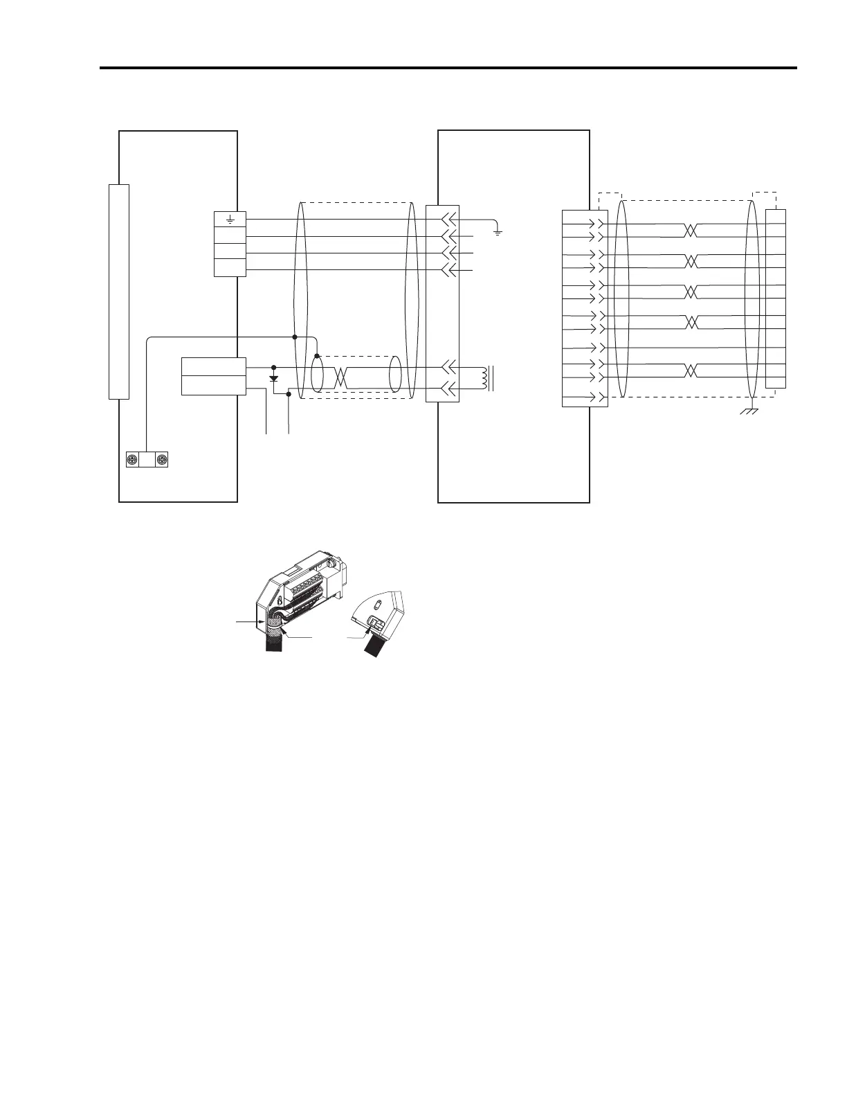
Wiring Example with TLY-A (TL-Series) Motors
BR+
BR-
W
V
U
AM+
AM-
BM+
BM-
IM+
IM-
+5VDC
ECOM
WHT/BLUE
GREEN
WHT/GREEN
GRAY
WHT/GRAY
BLACK
WHT/BLACK
RED
WHT/RED
1
2
3
4
5
10
14
6
12
S1
S2
S3
YELLOW
WHT/YELLOW
13
8
GND
SHIELD
5
3
2
1
7
9
0
1
2
3
4
5
6
7
8
9
10
11
12
13
14
15
4
3
2
1
W
V
U
43
44
Brake/Relay +
Brake/Relay -
+24V
COM
22
23
15
24
17
19
9
10
11
12
13
14
Motor
Brake
Cable Shield Clamp
Note 9
Three-phase
Motor Power
Motor Feedback
User-supplied
+24V dc Power Supply
(1 A max)
Motor Feedback
(CN2) Connector
Ultra3000 (230V) Drive
Note 13
Black
White
Control Interface
(CN1) Connector
Green/Yellow
Blue
Black
Brown
TLY-Axxxx-H (230V)
Servo Motors with
Incremental Feedback
Grounding Technique for
Feedback Cable Shield
Exposed shield secured
under clamp.
Cable Tie
2090-CFBM6DF-CBAAxx (flying-lead) or
2090-CFBM6DD-CCAAxx (with drive-end connector)
Feedback Cable
Note 12, 15
2090-CPBM6DF-16AAxx
Motor Power Cable
Note 12, 16
Refer to illustration (lower left)
for proper grounding technique.
Motor Feedback
(CN2) Connector
Motor Power
(TB1) Connector
Note 21
2090-UXBB-DM15
Motor Feedback Breakout Board
2090-CPWM6DF-16AAxx
cable for motor without brake.
 Loading...


