Rockwell Automation Publication DRIVES-AT005D-EN-P - May 2022 83
Appendix A Electrical Ratings, Recommended Protective Devices, and DC Bus Capacitance
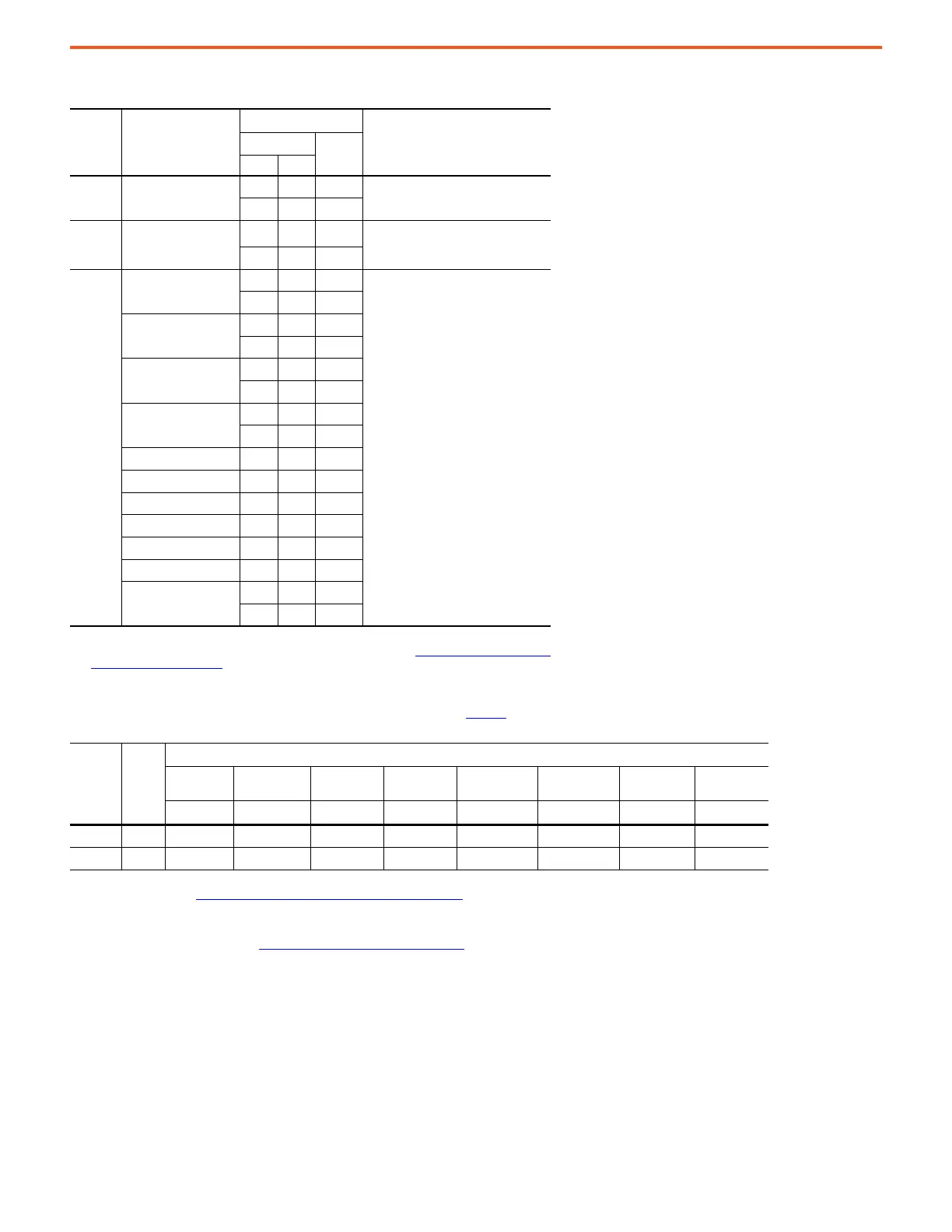
Table 21 - PowerFlex 755TM Non-regenerative Supply – Single and Dual Density, 690V AC (932V DC Output)
Cat.No
20JEH... Size
(1)
(1) Modules are available in single density and dual density. Modules can be paralleled to increase the rating. In this
table ‘1X’ means a single-density module, ‘2X’ means a dual-density module. See Paralleling PowerFlex 755TM Non-
regenerative Modules on page 41.
DC Output Rating
(1)
Internal Optional DC Bus Cap (uF)
(2)
(2) For paralleled modules sum the corresponding 1X and 2X internal optional capacitance values to obtain the overall
bus supply internal/optional DC bus capacitance value.
kW Rating
Cont.
AmpsND HD
F505 1X
561 - 602
7,000
-463497
F920 2X
1008 1082
14,000
-849911
20-750-
MN…
(3)
(3) Parallel configurations are built-up from separate enclosures and 20-750-MN… single-density 1X and dual-density
2X roll-in modules. See the PowerFlex 755TM IP00 Open Type Kits Technical Data, publication 750-TD101
.
1X/2X
1570 - 1686
Total internal uF values calculated
based on module size and quantity of
parallel modules
-12961392
2X/2X
2075 - 2227
-17131839
1X/2X/2X
2580 - 2769
-21302286
2X/2X/2X
3084 - 3311
-25462734
1X/1X/ 3084 - 3311
2X/x2X - 2546 2734
2X/2X/ 4094 - 4395
2X/2X - 3380 3628
1X/1X/ 5103 - 5478
2X/2X/2X/2X - 4213 4523
2X/2X/2X/2X/2X/2X
6112 - 6562
-50465417
Cat.No.
20JEH…
Module
Size
(1)
(1) Modules are available in single density and dual density. Modules can be paralleled to increase the rating. In this table, ‘1X’ means a single-density module, ‘2X’ means a
dual-density module. See Paralleling PowerFlex 755TM Non-regenerative Modules on page 41
for more information.
Maximum DC Bus Capacitance (uF)
(2)
(3)
(2) For paralleled modules, sum the corresponding 1X and 2X maximum external capacitance values to obtain the overall bus supply system maximum external DC bus
capacitance value.
(3) Select the fastest precharge ramp time that supports the total connected DC bus capacitance. Perform calculations to determine the required DC bus capacitance and
the system total DC bus capacitance. See DC Bus Capacitance Calculation Method on page 87
.
Precharge
Ramp
Precharge
Ramp
Precharge
Ramp
Precharge
Ramp
Precharge
Ramp
Precharge
Ramp
Precharge
Ramp
Precharge
Ramp
0.2 s 1.3 s 2.0 s 5.0 s 10 s 20 s 30 s 60 s
F505 1X 27,800 139,000 278,000 695,000 1,390,000 2,780,000 4,170,000 8,340,000
F920 2X 50,700 253,500 507,000 1,267,500 2,535,000 5,070,000 7,605,000 15,210,000

 Loading...


