B-2 Schematics
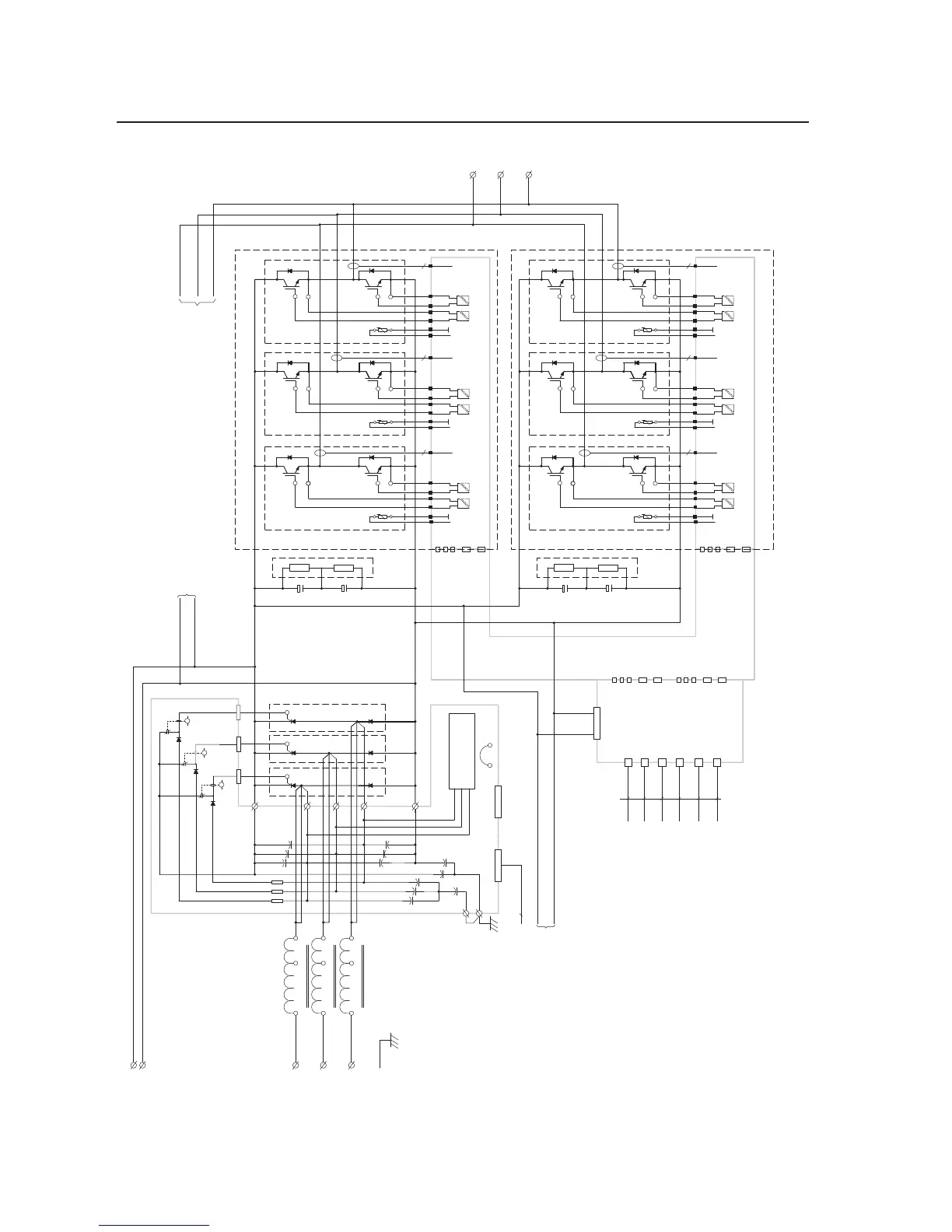
Power Circuitry for Drives with AC Input
W_LO
W_HI
TERM W
TERM V
V_HI
V_LO
TERM U
U_LO
U_HI
I_V
I_W
I_U
Power Board
4 4 4
X3
X8
X3
X2
X1
X9
X41
X4
Mains Voltage
Suppression
Rectifier Board
X13
X10
X11
X12
K3
K2
K1
X2
X1
X4
X5
Right-Hand Output Power Module
W_LO
W_HI
TERM W
TERM V
V_HI
V_LO
TERM U
U_LO
U_HI
I_V
I_W
I_U
Power Board
4 4 4
X3
X2
X1
X4
X5
Left-Hand Output Power Module
X14
X15
X16
X18
X20
X4
X5
X6
X8
X10
Adapter
Board
Fiber Optic Cables
H4 (UH)
H5 (UL)
H6 (VH)
H7 (VL)
H8 (WH)
H9 (WL)
From ASIC Board H8
From ASIC Board H9
From ASIC Board H10
From ASIC Board H11
From ASIC Board H12
From ASIC Board H13
X8
X9
X10
X11
X12
X3
X4
X5
X6
X7
Driver
Board
X11
X12
X13
X17
X19
X1
X2
X3
X7
X9
X6
From ASIC Board X2
DC+
DC-
To ASIC Board X6
5
X1 X2
X3
X1 X2
X3
X1 X2
X3
Line Reactor
L1 / R
L2 / S
L3 / T
X50
T1/ U
T2 / V
T3 / W
DC+
DC-
To Voltage Feedback Board J2
(On 700S Only)
To Voltage Feedback Board J1
(On 700S Only)
PE
X1
400V drives have
2 DC Bus Capacitors
in series and
and 3 in parallel.
600V drives have
3 DC Bus Capacitors
in series and
and 2 in parallel.
Figure B.1 Power Circuitry for Drives
with AC In

 Loading...