3-6 Access Procedures
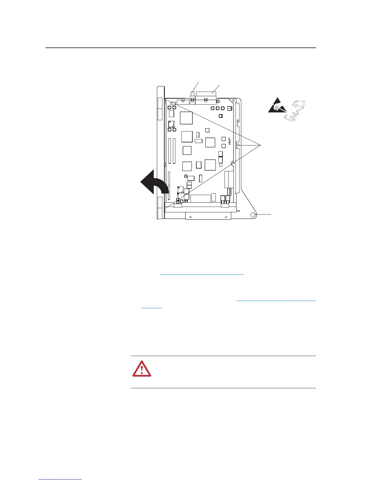
4. Remove the three screws that hold the control bracket and Phase I Main
Control circuit board to the control frame.
5. Remove the control bracket and Phase I Main Control circuit board.
Installing the 700S Phase I
Control Assembly
Install the 700S Phase I Control assembly in reverse order of removal, while
referring to Torque Specifications on page 3-2
.
Removing the 700S Phase II
Control Assembly
1. Remove power from the drive. Refer to Removing Power from Drive on
page 3-3.
Important: Before removing connections and wires, mark the connections
and wires to avoid incorrect wiring during assembly.
2. Unplug any fiber optic ControlNet and SynchLink cables from the
Control Assembly (if present).
Important: Minimum inside bend radius for SynchLink and ControlNet
fiber-optic cable is 25.4 mm (1 in.). Any bends with a shorter
inside radius can permanently damage the fiber-optic cable.
Signal attenuation increases with decreased inside bend radii.
=
J7 J2
Remove Three screws
Loosen captive
screw
!
ATTENTION: Hazard of permanent eye damage exists when
using optical transmission equipment. This product emits intense
light and invisible radiation. Do not look into fiber-optic ports or
fiber-optic cable connectors.

 Loading...