3-8 Access Procedures
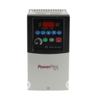
5. Carefully disconnect the ribbon cables from the sockets on the High
Power Fiber Optic Interface circuit board on the back of the control
mounting plate.
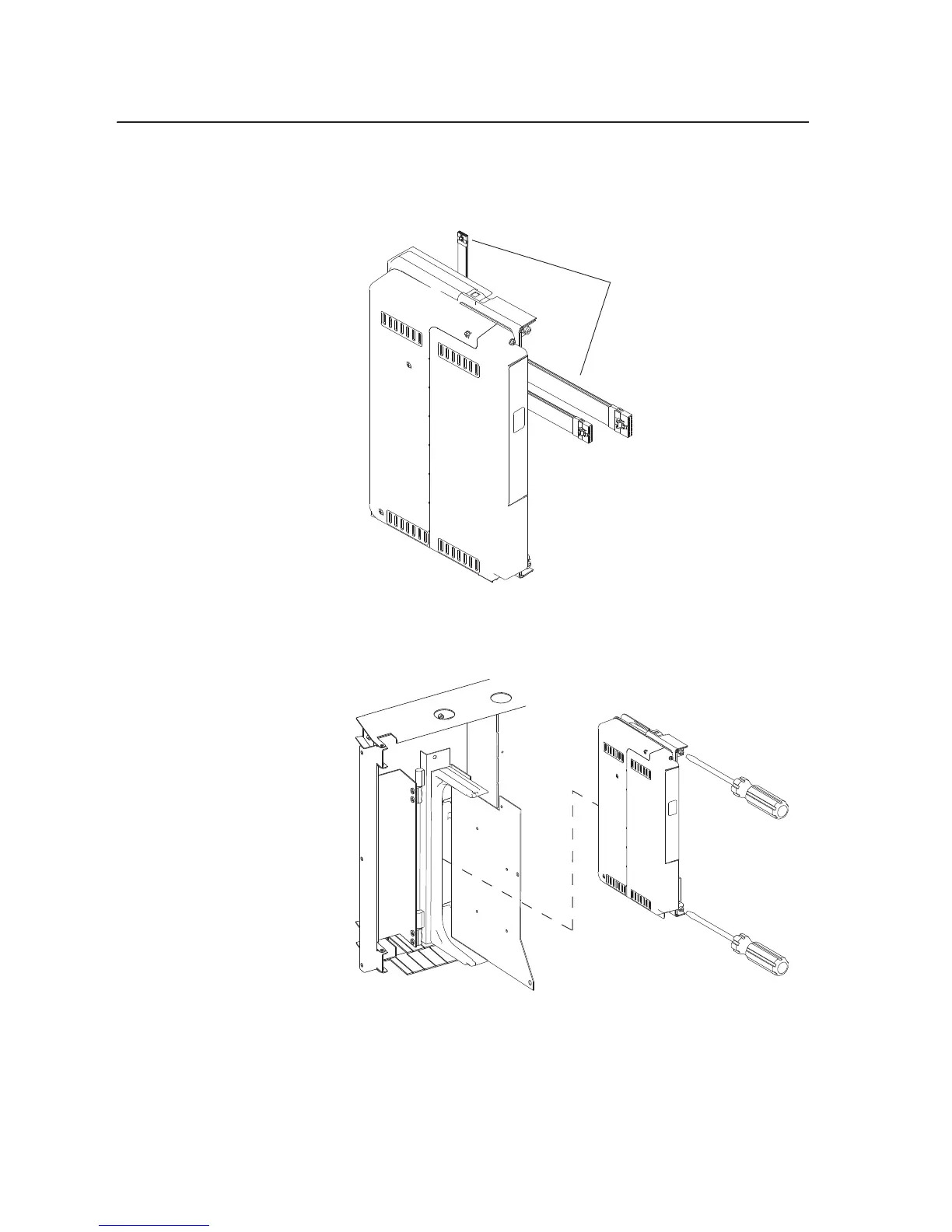
6. Loosen the two mounting screws on the front of the Control assembly
and slide the control cassette off the mounting bracket.
Installing the 700S Phase II
Control Assembly
Install the 700S Phase II Control assembly in reverse order of removal.
Disconnect ribbon cables.
Note: Control mounting plate
not shown for clarity only.
Note: Ribbon cables not shown
for clarity only.

 Loading...