Access Procedures 3-29
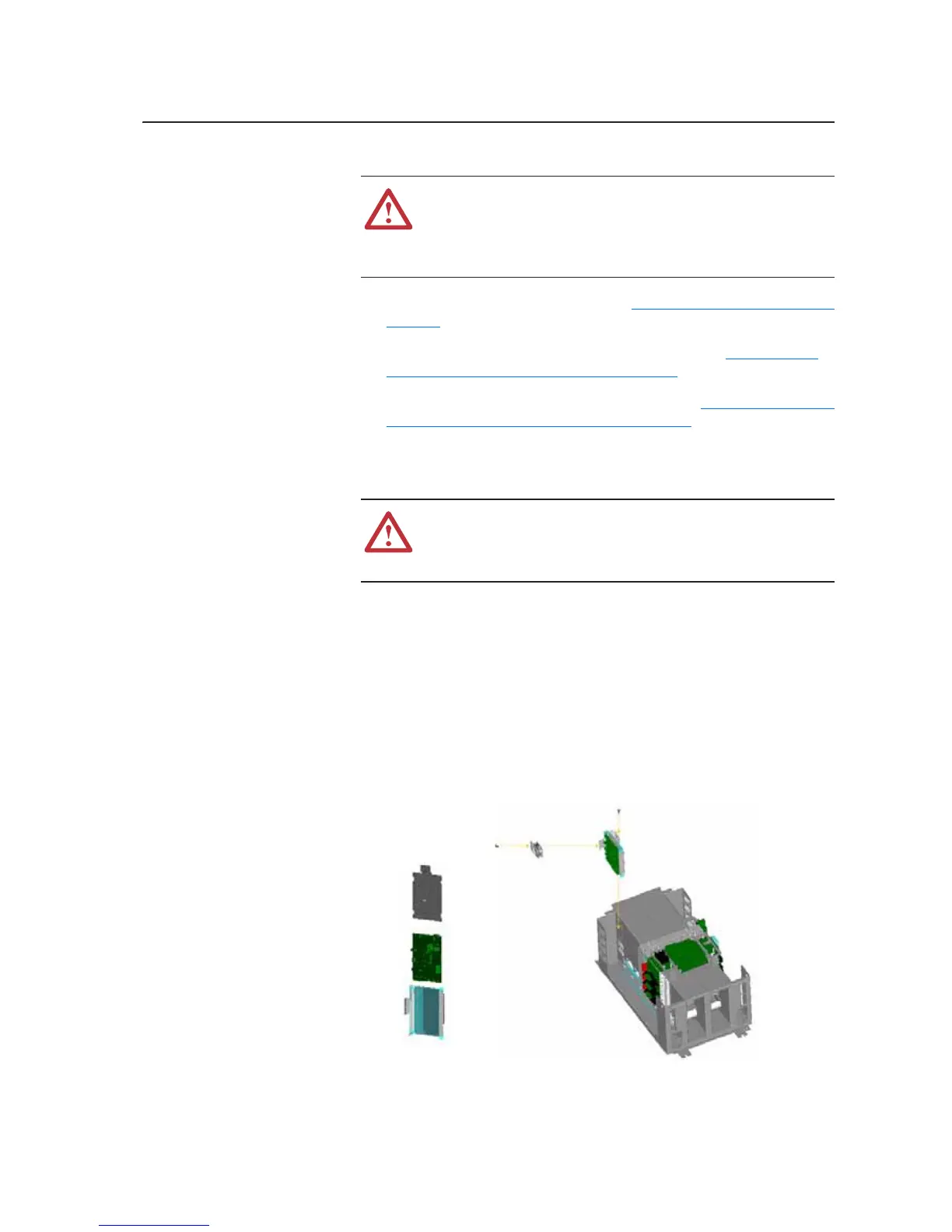
Removing the ASIC Circuit
Board
1. Remove power from the drive. Refer to Removing Power from Drive on
page 3-3.
2. Remove the covers from the power structure. Refer to Removing the
Covers from the Power Structure on page 3-15.
3. Remove the power structure for the drive. Refer to Removing the Power
Structure from the Drive Enclosure on page 3-27.
4. Carefully disconnect the fiber-optic cables from sockets (H1 - H7)
along the front of the ASIC board, and carefully set them aside.
Important: Minimum inside bend radius for fiber-optic cable is 25.4 mm (1
in.). Any bends with a shorter inside radius can permanently
damage the fiber-optic cable. Signal attenuation increases with
decreased inside bend radii.
5. Disconnect the other cables from sockets on the front of the ASIC board
and set them aside.
6. Disconnect the wire connected to the cover of the ASIC board.
7. Remove the fan from the ASIC board.
!
ATTENTION: The sheet metal cover and mounting screws on
the ASIC circuit board located on the power structure are
energized at (-) DC bus potential high voltage. Risk of electrical
shock, injury, or death exists if someone comes into contact with
the assembly.
!
ATTENTION: Hazard of permanent eye damage exists when
using optical transmission equipment. This product emits intense
light and invisible radiation. Do not look into fiber-optic ports or
fiber-optic cable connectors.
asic01.jpg
asic02.jpg

 Loading...