Component Test Procedures 2-3
Inspecting the Power Structure
1. Remove power from the drive. Refer to Removing Power from Drive on
page 3-3.
2. Remove the covers from the power structure. Refer to Removing the
Covers from the Power Structure on page 3-15.
3. Check components for burn marks, breakage or foil delamination on
circuit boards. Check all the boards on the power structure, including
those on the Output Power Modules and the Rectifying Module (if
present).
Replace any of these components without further testing if they show
evidence of burn marks, breakage or foil delamination.
Conducting Forward and
Reverse Biased Diode Tests
for Major Power Components
A forward biased diode test checks the semiconductor junctions between
the terminals and measures the voltage drop across those junctions. A
reverse biased diode test should find an open circuit, and the meter should
display a value close to zero (Ex. “.0L” = zero load).
Important: The actual voltage readings may vary depending upon your
equipment. If your readings are not near the indicated values in
the tables below, verify that the actual voltage measured is
consistent for the Rectifying module and Output Power
modules.
There is a series A and series B Rectifying circuit board. The tests you can
perform and the results of those tests vary depending on which series of
board is in your drive.
1. Remove power from the drive. Refer to Removing Power from Drive on
page 3-3.
2. Remove the covers from the power structure. Refer to Removing the
Covers from the Power Structure on page 3-15.
3. Disconnect the motor leads from the drive.
4. Conduct forward and reverse biased diode tests on the Rectifying
Module (if present) and the Output Power Modules.
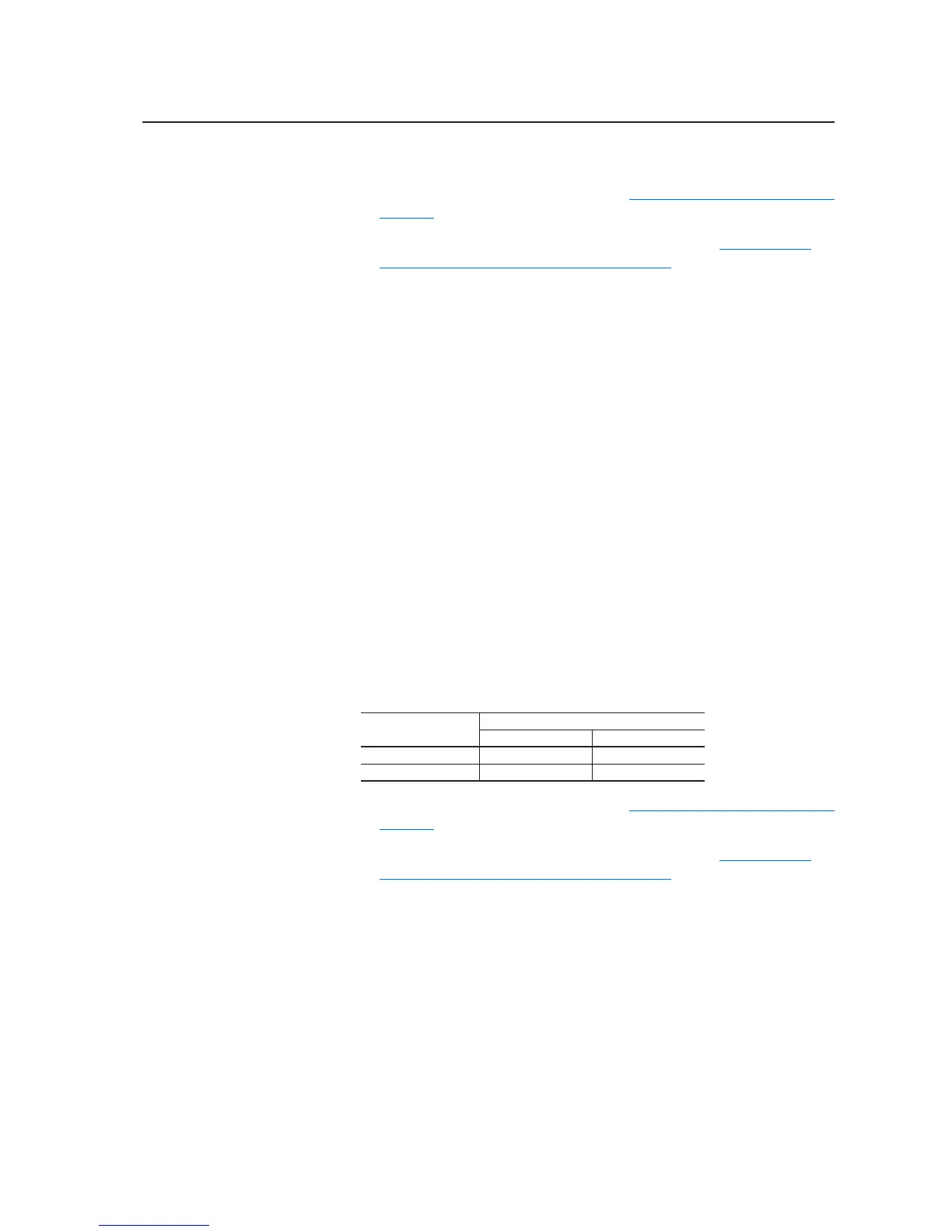
Voltage Class
Rectifying Circuit Board Catalog String
Series A Series B
400/480V AC 20-VB00459 20-VB00461
600/690V AC 20-VB00460 20-VB00462

 Loading...