3-40 Access Procedures
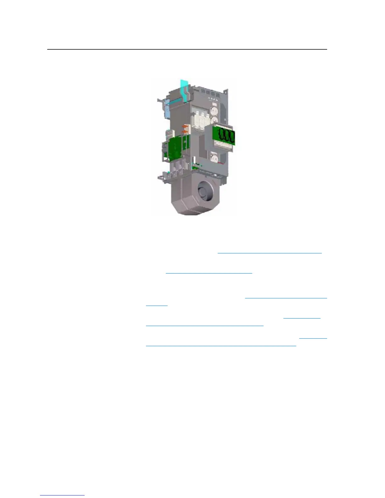
17. Remove the screws that secure the Output Power Module to the power
structure and remove the Output Power Module.
Installing the Right-Side
Output Power Module and
Rectifying Module
Important: If you replace the Output Power Modules in a 700H drive, you
must load information about the Power Modules into the Power
EEPROM (Refer to Loading the 700H EEPROM on page 4-1
).
Install the Output Power Module in reverse order of removal, while
referring to Torque Specifications on page 3-2
.
Removing the Fan Inverters
1. Remove power from the drive. Refer to Removing Power from Drive on
page 3-3.
2. Remove the covers from the power structure. Refer to Removing the
Covers from the Power Structure on page 3-15.
3. Remove the power structure from the drive cabinet. Refer to Removing
the Power Structure from the Drive Enclosure on page 3-27.
right_modules05.jpg

 Loading...