Access Procedures 3-31
Removing the Rectifying
Circuit Board
1. Remove power from the drive. Refer to Removing Power from Drive on
page 3-3.
2. Remove the covers from the power structure. Refer to Removing the
Covers from the Power Structure on page 3-15.
3. Remove the power structure for the drive. Refer to Removing the Power
Structure from the Drive Enclosure on page 3-27.
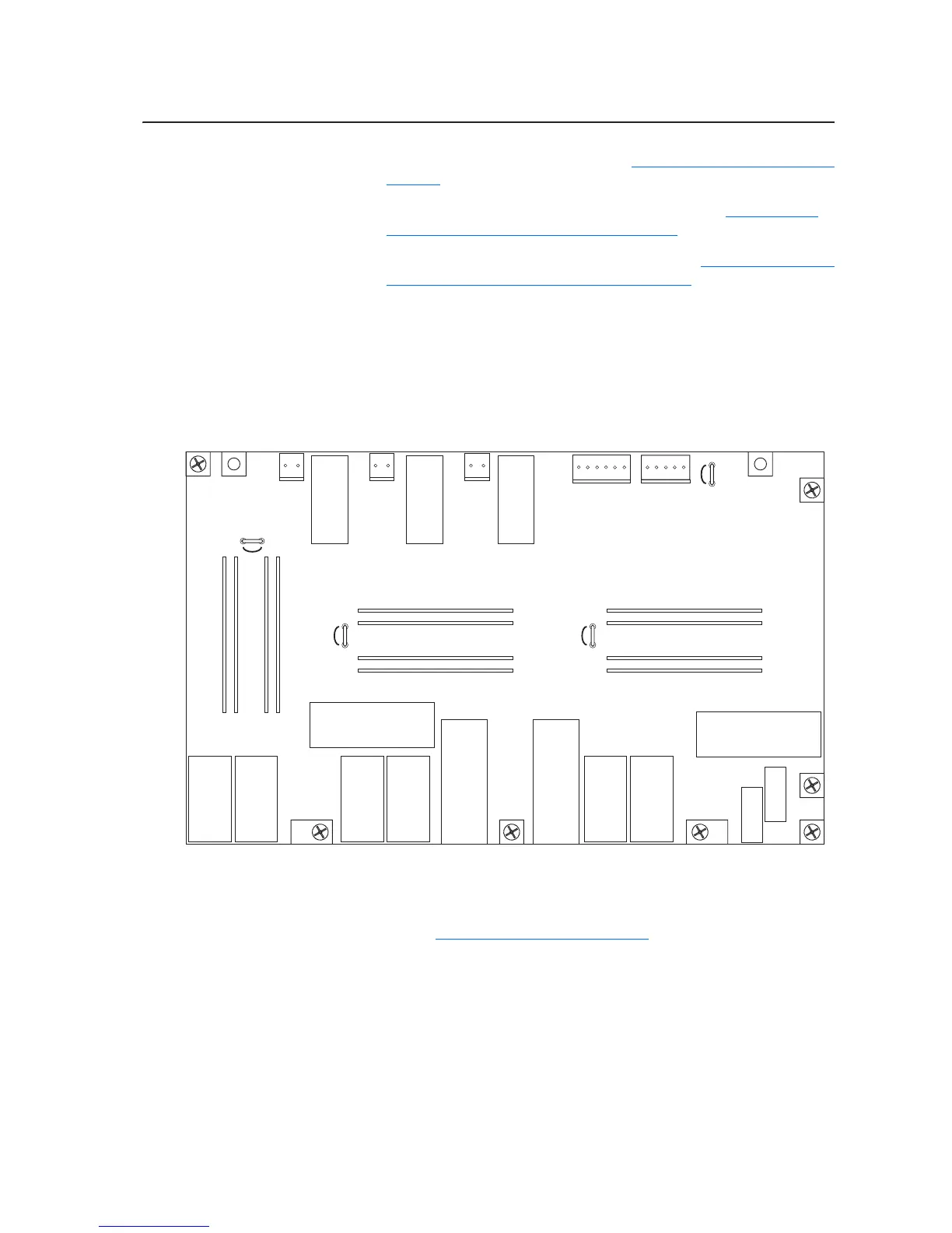
4. Disconnect all the wiring from connectors X10, X11, X12, X13 the
Rectifying board and carefully set it aside.
5. Remove the screws that secure the circuit board to the Rectifying
Module and remove the board.
Installing the Rectifying
Circuit Board
Install the Rectifying circuit board in reverse order of removal, while
referring to Torque Specifications on page 3-2
.
X13X6
X10X11
X12
X9 X100
X3
X2
X1
X4
X41
X8
X101
X50
J3
J7
J11
Series A Rectifying Board Shown

 Loading...