Component Test Procedures 2-9
Checking the Rectifying
Module (on AC Input Drives
Only)
Important: This procedure requires special equipment and training. Only
qualified and trained personnel should perform these
procedures.
There is a series A and series B Rectifying circuit board. The tests you can
perform and the results of those tests vary depending on which series of
board is in your drive.
1. Remove power from the drive. Refer to Removing Power from Drive on
page 3-3.
2. Remove the covers from the power structure. Refer to Removing the
Covers from the Power Structure on page 3-15.
3. Remove the Power Structure from the enclosure. Refer to Removing the
Power Structure from the Drive Enclosure on page 3-27.
4. Visually inspect the pre-charging resistors. If the pre-charging resistors
are damaged:
A. Replace the Rectifying Module (Refer to Removing the
Right-Side Output Power Module and Rectifying Module on
page 3-36).
B. Check the rectifiers and external connections for short-circuits.
C. Check the Output Power Modules (Refer to Conducting
Forward and Reverse Biased Diode Tests for Major Power
Components on page 2-3).
5. Verify that the plugs on the cable that connects X13 on the Rectifying
Board to X2 on the ASIC Board are properly seated.
6. Verify that the jumper at X50 on the Rectifying board is in place.
Taking Measurements on Rectifying Module
7. Disconnect connectors X13, X12, X11 and X10.
8. Perform resistance measurements, using a digital multimeter, on the
points listed in Table 2.I on page 2-10
or Table 2.J on page 2-10 (on AC
Three-Phase drives). These points are on the back of the X10, X11 and
X12 plugs which you have disconnected from the board. If the
Rectifying Module fails any of these tests, replace it (Refer to
Removing the Right-Side Output Power Module and Rectifying
Module on page 3-36).
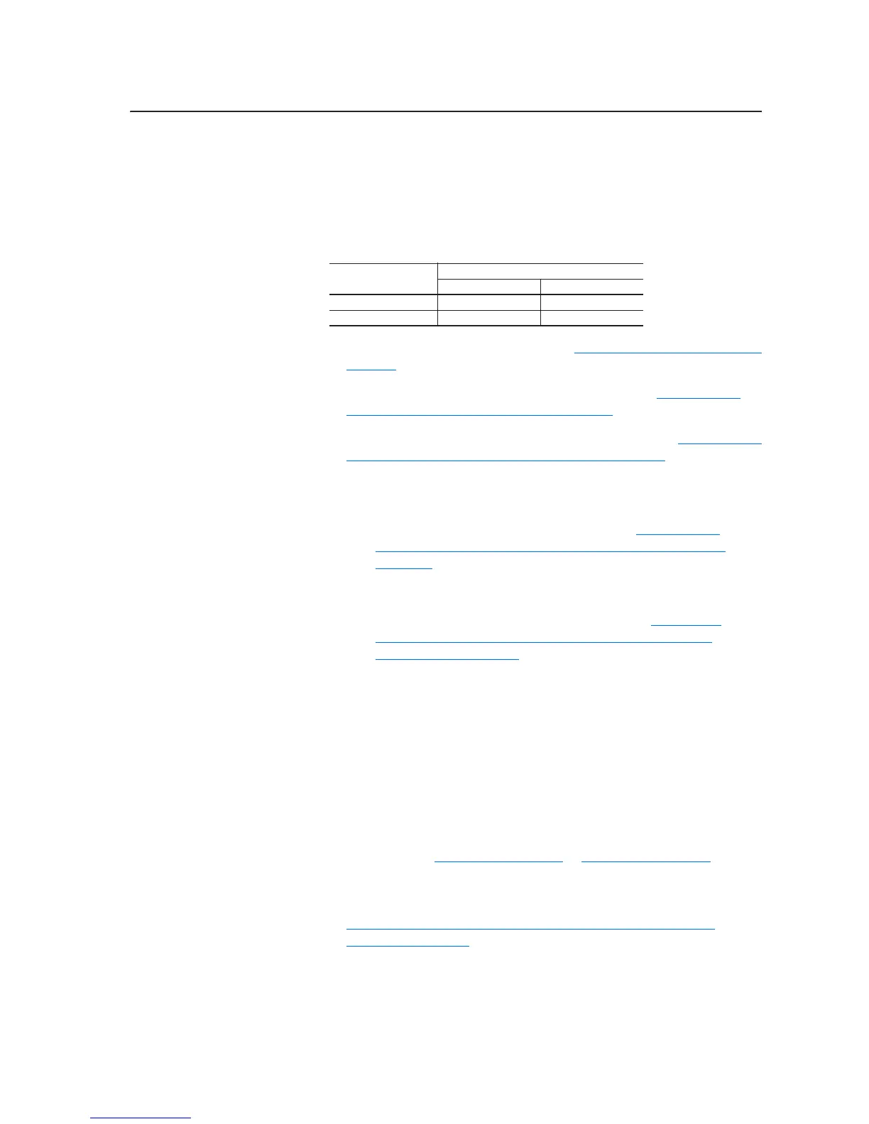
Voltage Class
Rectifying Circuit Board Catalog String
Series A Series B
400/480V AC 20-VB00459 20-VB00461
600/690V AC 20-VB00460 20-VB00462

 Loading...