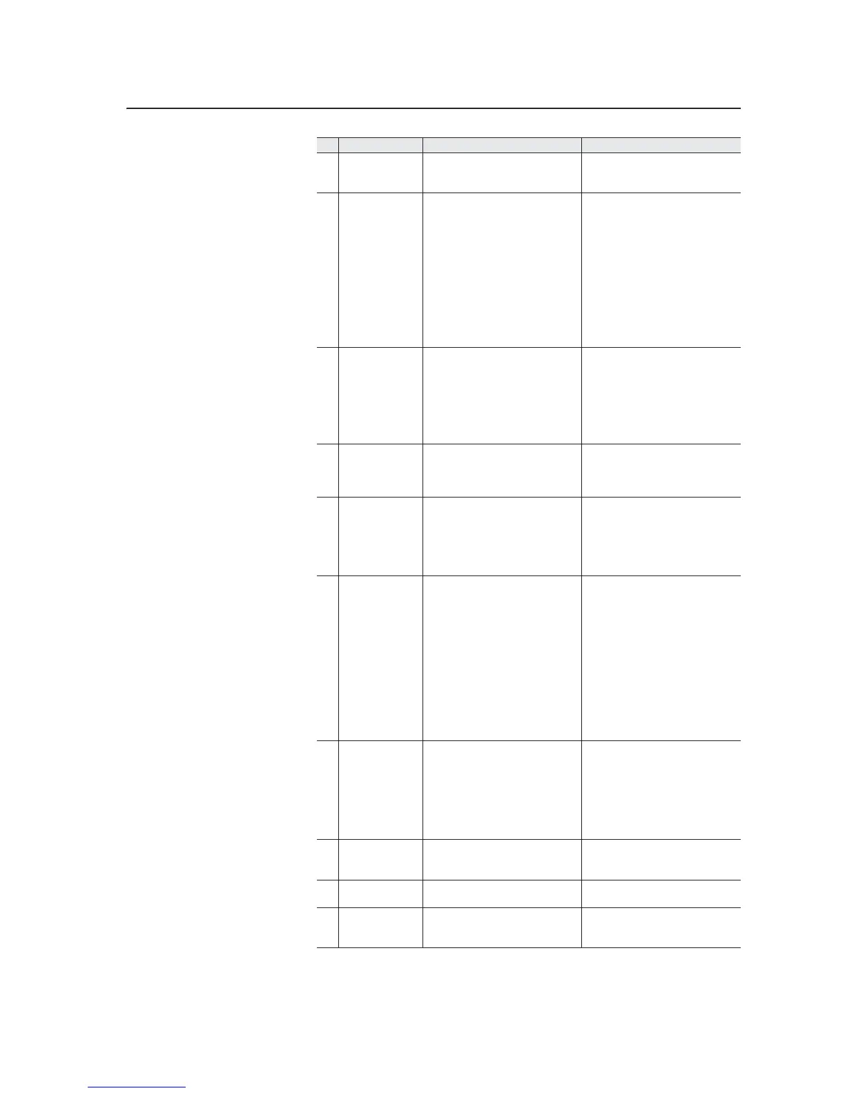
Troubleshooting and Error Codes 1-7
35 Parameter
Chksum
The checksum read from the
EEPROM does not match the
checksum calculated
• Cycle power
• Replace Main Control Board
38 Brake OL Trip The calculated temperature of the
dynamic braking resistor is too high.
The temperature is calculated by a
thermal model.
If the resistor is internal, the model
uses resistor characteristic stored in
the power structure EEPROM
memory.
If the resistor is external, the model
uses values of parameters 416
[Brake PulseWatts] and 417 [Brake
Watts].
• Verify actual temperature of
brake:
• If hot, wait for brake to cool
• If cold, cycle power to the drive
• If cold, verify [Brake PulseWatts]
and [Brake Watts] are correct.
• Configured with parameter 369
[Brake OL Cnfg]
39 PowerEE CRC Fail The CRC of the data stored in the
Power Board EEPROM does not
match the stored CRC.
• Cycle power
• In High Horse Power units, check
communication bus lines - 10 pin
connector in Main Control Board,
High Horse Power interface
board, and fiber optic cable
connections.
40 SLink Mult Oflow A SynchLink Multiplier Overflow has
occurred. Parameter 927 [SL Mult
State] displays SynchLink multiplier
overflow errors.
Configured with parameter 390 [SL
MultErr Cnfg]
41 Ridethru Timeout The drive has been in a bus loss
ride-through condition for more than
two seconds (default). The
ride-through timeout can be
configured in parameter 407 [Power
Loss Time].
• Verify the AC Line.
• Verify the value in [Power Loss
Time].
42 DC Bus Undervolt Bus voltage has fallen below the level
configured in parameter 409 [Line
Undervolts].
• Verify the AC Line.
• In frames 1-4, and 9 - 13 verify
the precharge resistor is
present. (With power off, there
should be a resistance between
DC+ and BR+).
• In frames 5 & 6, check the
precharge board for errors. See
the precharge board LED for
fault sequence.
• Configured with parameter 393
[BusUndervoltCnfg]
43 VoltageFdbk Loss Loss of Motor or DC Bus Voltage
Feedback has occurred because of a
communication failure between Motor
Control and Voltage Feedback board.
• Check the communication line
between Motor Control (MC) and
Voltage Feedback board.
• Replace the Voltage Feedback
board.
• Configured with parameter 394
[VoltFdbkLossCnfg]
44 Runtime Data Rst Runtime data (hours, energy) has
been reset to zero due to a checksum
error.
45 Enable Health Safety circuit is active. • Check input signal to the Safety
circuit.
46 Interp Out Synch Interpolator for position feedback lost
synchronization with Velocity Position
Loop (VPL).
Configured with parameter 378
[Interp Flt Cnfg]
No. Name Description Action (if appropriate)

 Loading...