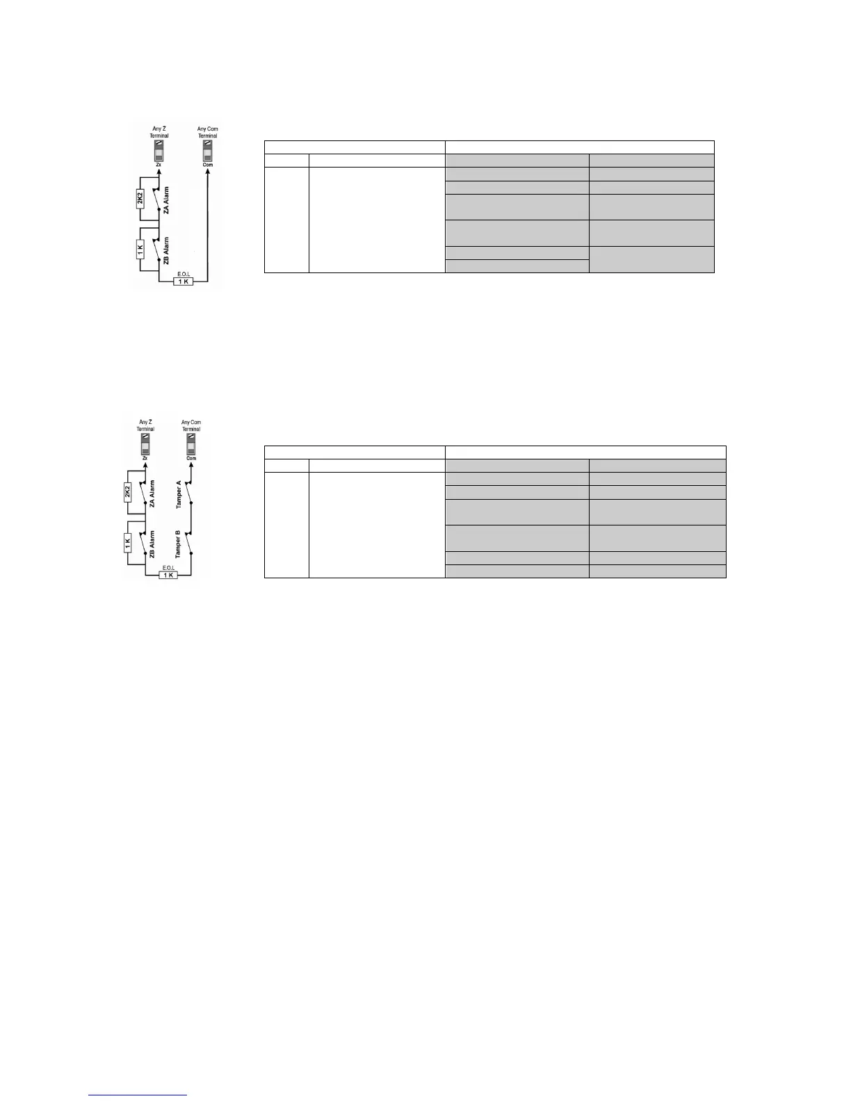
If your security installation does not require tamper or wire fault recognition, connect the detection devices as
shown in the next figure and ensure the zone wiring attributes are programmed as shown in the next table.
This setup will communicate the violated zones to the control panel which will display them on the keypads. Do
not use devices with N.O. contacts in this zone setup, as this will cause the zones to remain in alarm.
A.2.2. ZONE DOUBLING with N.C. CONTACTS, with EOL RESISTOR, with TAMPER & WIRE FAULT
RECONGNITION
If your security installation requires tamper (open circuit) and wire fault (short circuit) recognition, connect the
detection devices with a 1K end of line (EOL) resistor, as shown in the next figure and ensure the zone wiring
attributes are programmed as shown in the next table. This setup will communicate the violated zones to the
control panel which will display them on the keypads. The control panel will also communicate any open loops
(tamper trouble) and/or short circuits (wire fault trouble) as per Tamper / Wire Fault Recognition Options. Do
not use devices with N.O. contacts in this zone setup, as this will cause the zones to remain in alarm
 Loading...