1-5
MODEL 54 C SECTION 1
INSTALLATION
CAUTION
DO NOT apply power to the instrument
until all electrical connections are verified
and secure. AC connections and groun-
ding must be in compliance with UL 508
and/or local electrical code.
NOTE
For best EMI/RFI protection the output
cable should be shielded and enclosed in
an earth grounded rigid metal conduit.
Connect the cable’s outer shield to either
earth ground terminal on TB2, Figur
e 1-7.
The sensor cable should also be shielded.
Connect the outer shield to earth ground
via terminal 1 of TB1, Figure 1-7 If the outer
shield is braided an appropriate metal
cable gland fitting may be used to connect
the outer braid to earth ground via the
instrument.
NOTE
The user must provide a means to discon-
nect the main power supply in the form of cir-
cuit breaker or switch. The circuit breaker or
the switch must be located in close proximity
to the instrument and identified as the dis-
connecting device for the instrument.
NOTE
HART
®
communications not available.
Current output 1 switch must be in single
loop position. See Figur
e 1-7.
1.3.1 Analyzer Wiring. Figure 1-7, Figure 1-8 and
Figur
e 1-9 show how the analyzer should be wired.
A. Connect power input and output wiring per
Figur
e 1-7.
B. Wire inductive (Toroidal) sensors per Figur
e 1-9 or
wire contacting sensor per Figure 1-8.
NOTE
Do not allow earth ground (TB 1-1) to short
(contact) TB 1-2 inner drain, if this occurs
a ground loop may give inaccurate con-
ductivity readings.
1.3.2 Input Power Selection (Code -08). The Model
54C -08 is field selectable for 115Vac or 230Vac
50/60Hz. Refer to Drawing Number 400054C06.
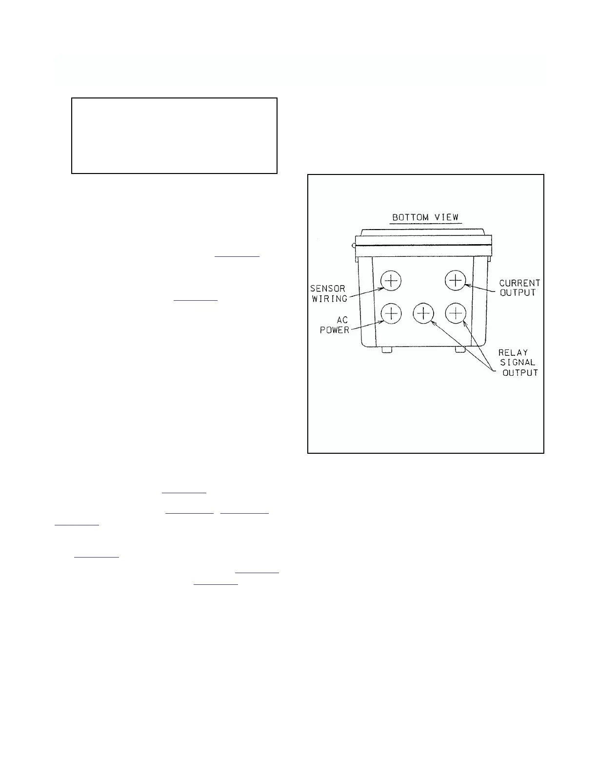
FIGURE 1-6. Conduit Openings