5-6
MODEL 54 C SECTION 5
DIAGNOSTICS AND TROUBLESHOOTING
Not all problems that you encounter will be typical. If
you are unable to resolve your problem using the
Quick Troubleshooting Guide, T
able 5-2, then try the
step by step approach offered in this section.
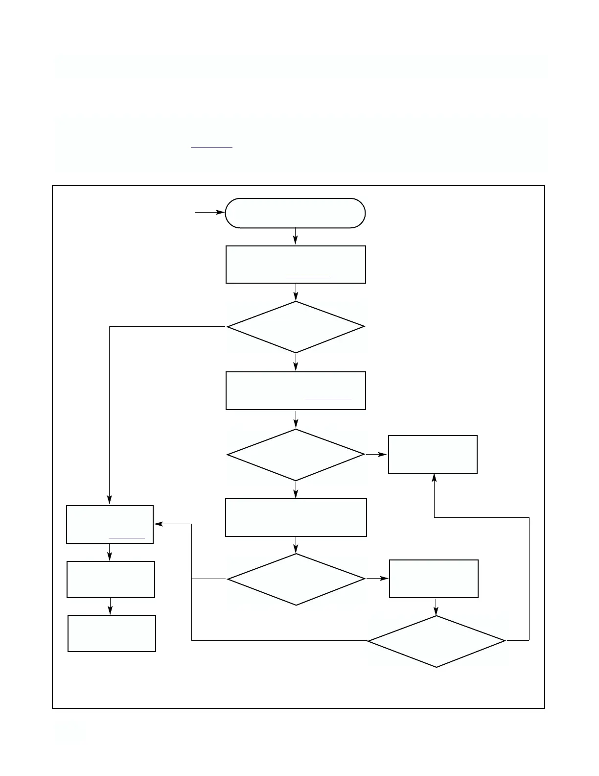
Step 1 Follow the applicable troubleshooting flow
chart:
Step 2 Refer to the tests and instructions indicated by
the flow chart to diagnose the problem.
Conductivity Measurement
Problem (in the process)
Remove sensor from process and
place sensor in air. Zero instru-
ment. Refer to Section 4.1.
OK?
OK?
Place sensor in process and stan-
dardize. Refer to Section 4.3.
Check wiring
for short
NOTE:
Before starting this procedure make
sure that all wiring is correct.
YES
YES
NO
NO
Does problem
still exist?
YES
NO
5.4 SYSTEMATIC TROUBLESHOOTING
Check diagnostic
messages
Refer to Table 5-1
Restart
Analyzer
Check for ground
loops and/or improp-
er installation
Remove sensor from process and
test in known conductivity solution
OK?
Consult Service
Center
YES
NO
FIGURE 5-1. TROUBLE SHOOTING FLOW CHART