8-1
MODEL 54 C SECTION 8
DESCRIPTION AND ORDERING INFORMATION
SECTION 8.0
DESCRIPTION AND ORDERING INFORMATION
• USES EITHER CONTACTING OR INDUCTIVE CONDUCTIVITY SENSORS to meet
most application requirements.
•
EASY-TO-USE INTERFACE spells out each operation.
• HEAVY DUTY NEMA 4X (IP65) enclosure of epoxy-painted cast aluminum.
• FULLY DESCRIPTIVE DIAGNOSTIC MESSAGES.
• TWO INDEPENDENT OUTPUTS for conductivity and temperature.
• THREE ALARMS WITH PROGRAMMABLE LOGIC plus one dedicated fault alarm.
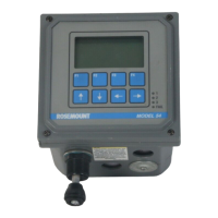
8.1 FEATURES AND APPLICATIONS
The Model 54 C Conductivity Analyzer, with the appro-
priate sensor, monitors and controls conductivity in a
variety of industrial processes using the most advanced
technology available.
The analyzer can use either contacting or inductive
(Toroidal) conductivity sensors. The sensor type is
selected by keyboard entry. This feature allows the
user to stock one instrument for most conductivity
applications.
The analyzer is housed in a rugged NEMA 4X (IP65)
weatherproof, corrosion resistant enclosure of epoxy-
painted cast aluminum. It is suitable for panel, pipe
or wall mounting. All functions are accessible through
the front panel membrane keyboard which features
tactile feedback. The large dot-matrix liquid crystal
display continuously indicates conductivity, tempera-
ture, current output and alarm setpoints. Three levels
of security are available: 1) calibration, 2) output
range and alarm setpoint adjustment, and 3)
advanced configuration. A hinged front panel pro-
vides convenient wiring access.
The two independent, isolated outputs provide 4-20
or 0-20 mA signals for conductivity and temperature.
Both output ranges are programmable within the
measurement ranges of conductivity and tempera-
ture. A hold output mode allows manual control dur-
ing routine sensor maintenance. During hold mode
the current outputs will be held at a preset or last
process value.
In the event of a fault, the analyzer will display a
descriptive diagnostic message, illuminate a red LED
on the front panel and drive the outputs to preselec-
table fault mode values. A dedicated fault relay may
be used to provide a visual or audible alarm to an
operator.
Three process alarms are a standard feature. All
alarms have programmable high or low activation,
independent setpoints, adjustable hysteresis (dead-
band) and time delay. One relay may be configured as
a timer for automatic chemical cleaning of the sensor.
Green LED’s on the front panel indicate the status of
each of the three alarm relays.
Standardization is easily accomplished by simply
immersing the sensor in a known solution and enter-
ing the value. With a two point calibration, the analyz-
er will automatically calculate the temperature slope
of the solution.
The Model 54C utilizes either a PT-100 or a PT-1000
RTD located in the sensor to display temperature and
compensate the conductivity reading for changes in
process temperature. Manual temperature compen-
sation is also keyboard selectable.