1-4
1.3 WIRING THE ANALYZER
MODEL 54 C SECTION 1
INSTALLATION
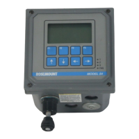
FIGURE 1-4. Wall Mounting
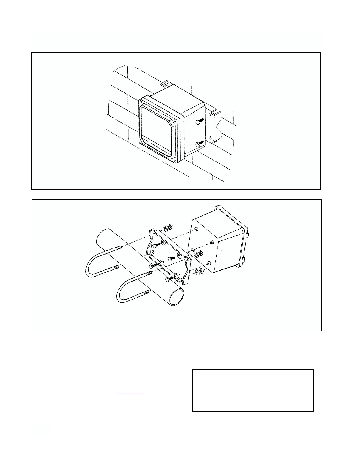
FIGURE 1-5. Pipe Mounting
There are five conduit openings in the bottom of the ana-
lyzer housing which accommodate 1/2 inch conduit fit-
tings or PG 13.5 cable glands. The conduit opening on
the left (rear) is for AC power input; the center (rear) and
right (rear) are for relay signal outputs and the opening
on the right (front) is for current output wiring and the left
(front) is for sensor wiring. Refer to Figur
e 1-6. AC power
wiring should be 14 gauge or greater.
Mount 1/2 inch conduit fittings using weather seals.
Bring all wiring through the conduits to the analyzer
terminal strips. Mount NEMA 4X or IP65 conduit plugs
(supplied) into unused holes in the base of the analyz-
er.
CAUTION
Be sure to place sensor wiring in a sepa-
rate conduit from power wiring. Sensitivity
and stability of the instrument is impaired if
input wiring is not grounded.