30
MODEL 1054B pH/ORP SECTION 4.0
CONFIGURATION
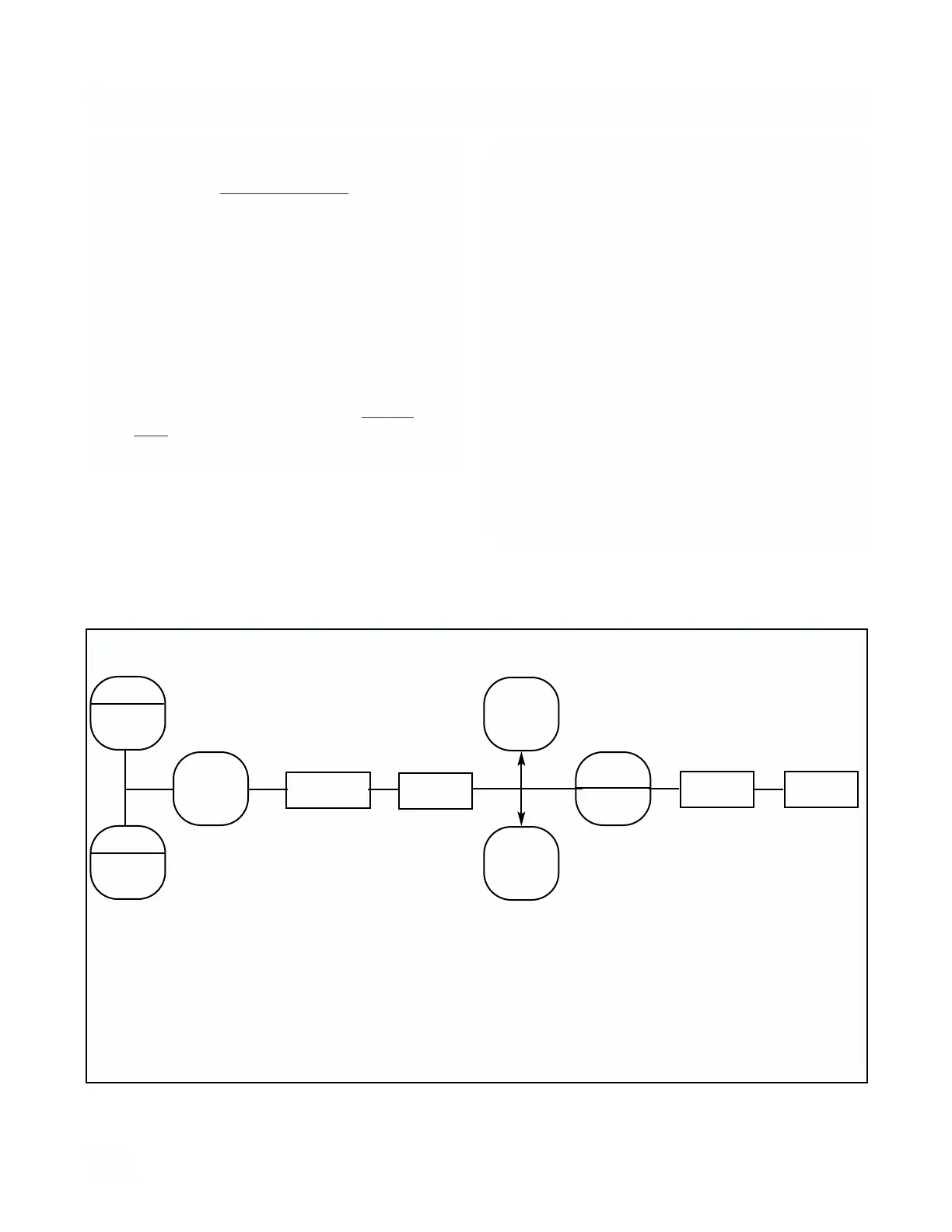
4.10 ALARM SETPOINT. The alarm setpoints should
be adjusted after completing the configuration proce-
dure as outlined in Sections 4.2 to 4.9.
1. Press the PV key to ensure that the analyzer is
not in Set Mode.
2. Press the ALARM 1 or ALARM 2 key. SP1 or SP2
will show briefly, followed by the Alarm 1 or
Alarm 2 setpoint.
NOTE
If the alarm is set to OFF or FAULT
(Alarm 2 only), the analyzer will display
OFF or FLt respectively (Refer to Section
4.2.1, Alarm Setup).
NOTE
Alarm logic may be changed from normal-
ly open (N.O.) to normally closed (N.C.) by
cutting circuits on the power supply PCB
(W-5, W-7, W-9) and adding jumpers (W-
4, W-6, W-8).
3. SELECT to adjust the value. The display will
acknowledge briefly with AdJ followed by the
Numeric Display with digit flashing.
4. SCROLL (
é
) and SHIFT (
ç
) to display the
desired value.
5. ENTER value into memory.
6. Repeat Steps 2 to 5 for the second setpoint.
ZERO
ALARM
1
F.S .
ALARM
2
ACCESS
é
AdJ
SP1/2
ç
SELECT
ç
SELECT
ENTER
Press
Once
Press
Once
Displays
Briefly
Displays
Briefly
Numeric
Display
Change to
desired
value
Press
Once
Numeric
Display
of
Setpoint
FIGURE 4-4. Alarm Setpoint