Reference Manual
00809-0100-4792, Rev CA
August 2010
Rosemount 1495, 1496
4-10
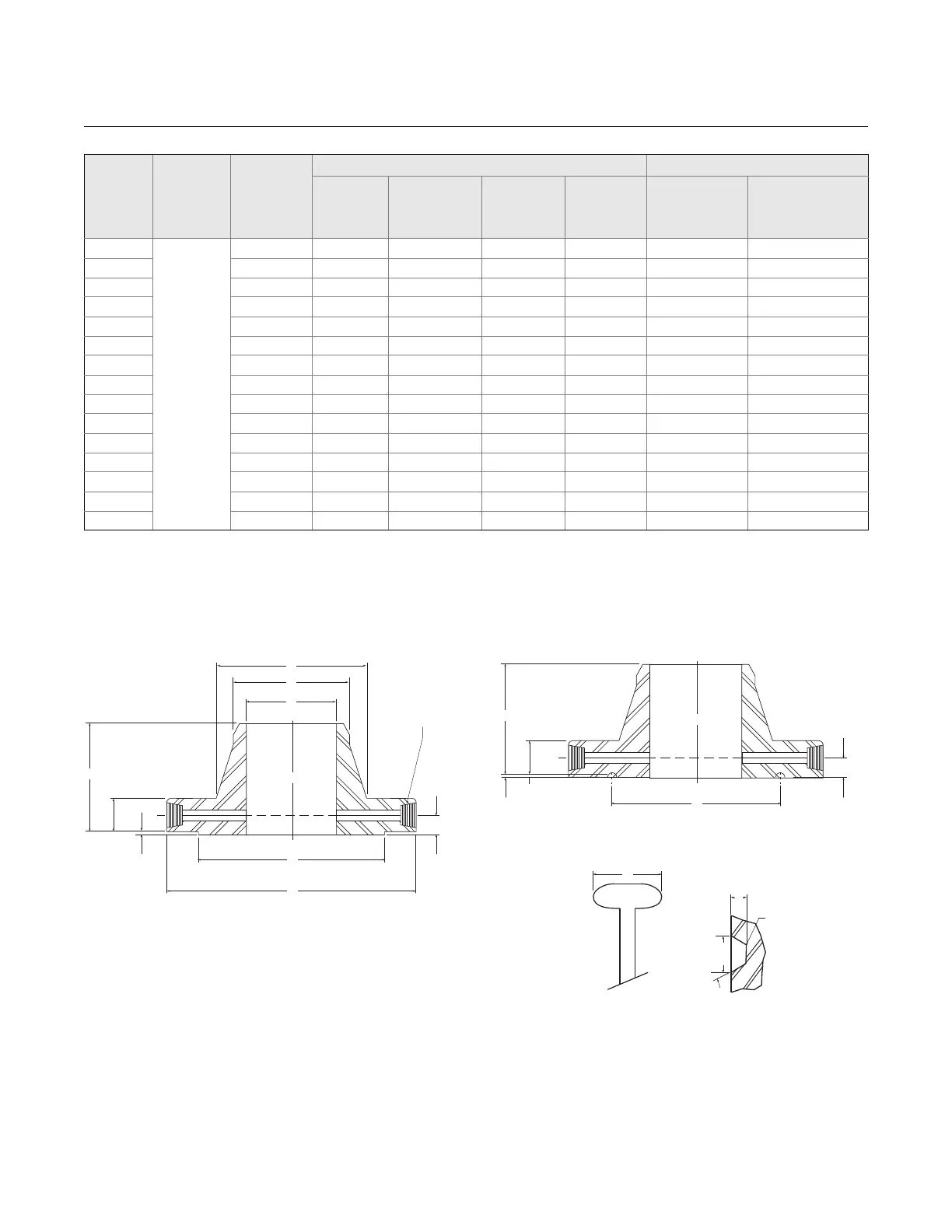
Figure 4-6. Class 2500
(1)
Nominal
Pipe Size
Bore B
Diameter
of
Pressure
Conn-
ection TT
Drilling Template Length of Stud Bolts
(2)(3)
(4)
Diameter of
Bolt Circle
Number of
Holes
Diameter of
Holes
Diameter of
Bolts
Raised Face Ring Joint
1
1
/4 4.00 4 1.00
7
/8 6.00 6.25
1
1
/2
1
/4 4.88 4 1.12 1 6.25 6.50
2
1
/4 6.50 8 1.00
7
/8 6.00 6.50
2
1
/2
1
/4 7.50 8 1.12 1 6.50 7.00
3
3
/8 8.00 8 1.25 1
1
/8 7.25 7.25
4
1
/2 9.50 8 1.38 1
1
/4 8.00 8.50
6
1
/2 12.50 12 1.50 1
3
/8 10.50 11.00
8
1
/2 15.50 12 1.75 1
5
/8 11.75 12.25
10
1
/2 19.00 12 2.00 1
7
/8 13.50 14.00
12
1
/2 22.50 16 2.12 2 15.00 15.75
14
1
/2 25.00 16 2.38 2
1
/4 16.25 17.52
16
1
/2 27.75 16 2.62 2
1
/2 17.75 19.00
18
1
/2 30.50 16 2.88 2
3
/4 19.75 21.00
20
1
/2 32.75 16 3.12 3 21.50 22.50
24
1
/2 39.00 16 3.62 3
1
/2 24.50 26.00
(1) All other dimensions are in accordance with ASME B16.5.
(2) Bolt lengths for raised face flanges include allowance for orifice and gasket thickness of 0.25 in. for NPS 1-12 and 0.38 in. for NPS 14-24. Bolt lengths for ring
type joint flanges include allowance of 0.62 in. for NPS 1-10, 0.75 in. for NPS 12-18, and 0.88 in. for NPS 20.
(3) In conformance with ASME B16.5, stud bolt lengths do not include point heights.
(4) Bore is to be specified by the purchaser.
X
A
B
1
R
O
Raised Face
Y
C
0.25 0.94
1/2 NPT (1)
1
P
Ring Type Joint
Y
C
E
0.75
Special One or Two
Piece Ring and
Orifice Plate Assembly
W
Groove
Detail
E
F
23 deg.