Inputs and Outputs
16 AC-215 Installation Manual
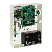
3.1.10 Card Readers
Two card readers can be connected to the ACU. The following should be
defined:
Single door controller
Door 1 – Reader 1 IN/OUT/Auxiliary
Reader 2 – IN/OUT/Auxiliary
Double door controller
Door 1 – Reader 1 IN/OUT
Door 2 – Reader 2 IN/OUT
The readers can be assigned to a single or double door controller’s door as an
IN or OUT reader and can activate the auxiliary output in a single door
configuration.
The reader’s tamper connects to the ACU and can generate an alarm. The
reader’s green LED input is activated by the ACU when in the Card and PIN
secure mode to inform the user to enter his personal PIN number after entering
his card.
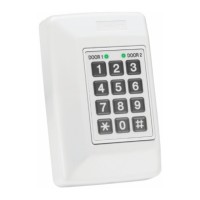
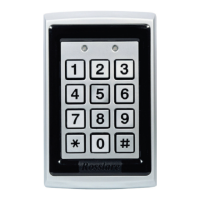
3.1.11 Keypad
Two keypads can be alternatively connected to the ACU on Reader1 and
Reader2 terminals. The following should be defined:
Single door controller
Door 1 – Keypad – Reader 1 IN/OUT
Keypad – Reader 2 IN/OUT
Double door controller
Door 1 – Keypad – Reader 1 IN/OUT
Door 2 – Keypad – Reader 2 IN/OUT
The keypad type must be a Rosslare format keypad.
A keypad has to be connected for any reader mode that requires PIN code
entries, such as Card or PIN, PIN only or Card and PIN (Secured mode).
 Loading...