EasyManuals Logo

Rosslare AC-215 Hardware Installation Manual

Rosslare AC-215
42 pages
To Next Page IconTo Next Page
To Previous Page IconTo Previous Page
Page #24 background imageLoading...
Page #24 background image
Wiring
24 AC-215 Installation Manual
6. Wiring
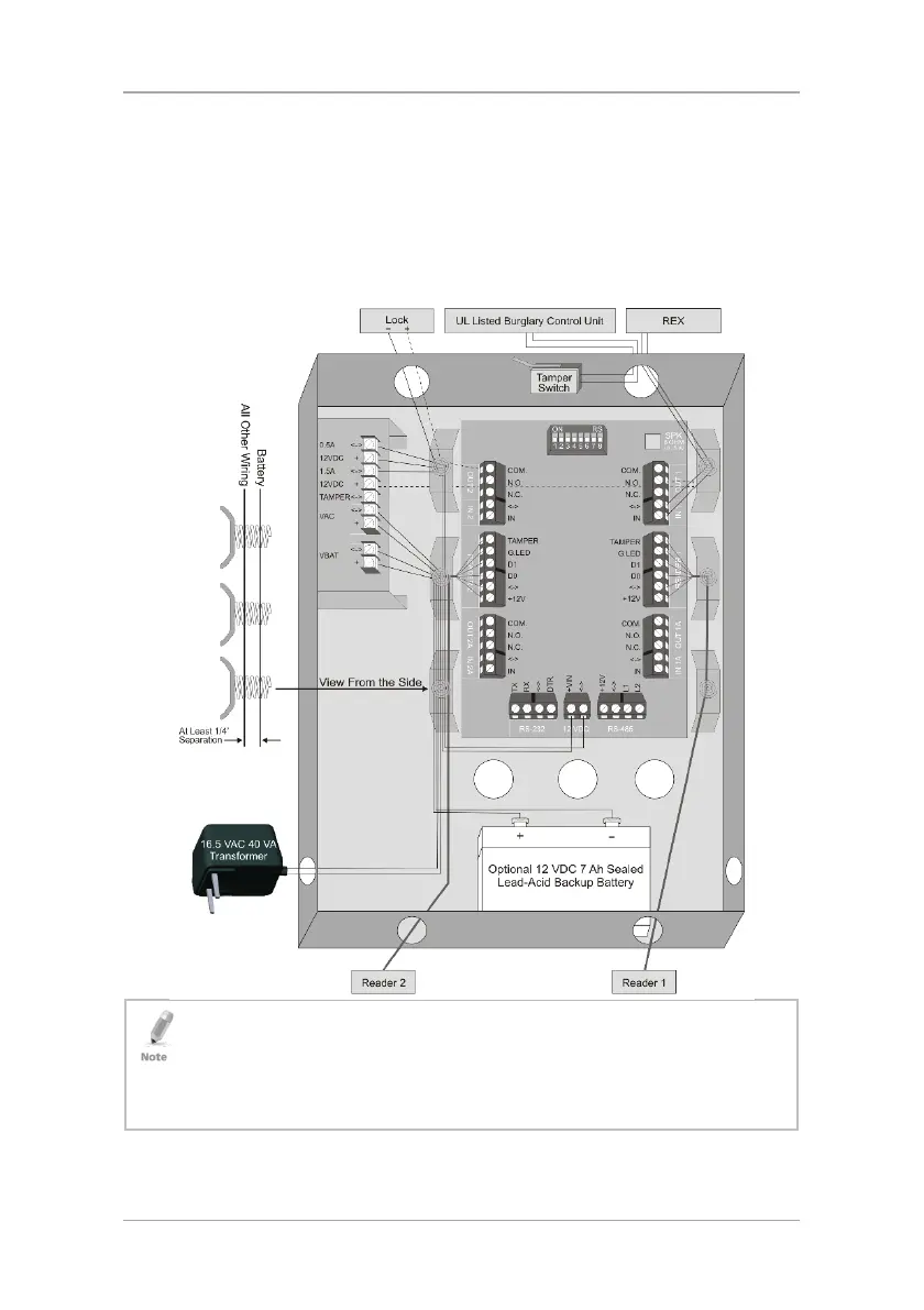
6.1 General Wiring Diagram
Figure 5 illustrates the general wiring layout of the AC-215.
Figure 5: Wiring
For UL installations, the following signal lines are not allowed to be run outside
of the protected area:
12 VDC 1.5 A + and (-)
12 VDC 0.5 A + and (-)
Relay contacts OUT1: COM., N.O., and N.C.

Table of Contents

Other manuals for Rosslare AC-215

Questions and Answers:

Question and Answer IconNeed help?

Do you have a question about the Rosslare AC-215 and is the answer not in the manual?

Rosslare AC-215 Specifications

General IconGeneral
BrandRosslare
ModelAC-215
CategoryGateway
LanguageEnglish

Related product manuals