Connecting between MD-N33 and AC-215
AC-215 Installation Manual 35
B. Connecting between MD-N33 and
AC-215
This manual is written as step by step instruction. It is very important to follow
the right order.
B.1 Hardware Requirements
2 Standard Telephone cables – RJ11 plugs in both sides
Standard Serial cable D-type 9 pin (Female connectors at both sides)
Rosslare's MD-14 (RS-232 to RS-485 converter)
2 Rosslare's MD-N33 (Modem to serial gateway)
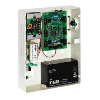
Rosslare's AC-215 panel
B.2 Topics
The telephone numbers shown at the examples below are for illustration
purpose only.
Before permanent modem installations, the modem that has to be
connected to the panel must initialize at PC running the AxTraxNG
software.
B.3 Connections – PC Side
1. Connect a 9 VDC adapter to the first MD-N33.
2. Make sure that the power LED (Red) is on.
3. Connect the PC, using a free COM port, to the MD-N33 with cross serial
cable.
4. Connect the MD-N33's RJ11 jack to telephone line using the telephone
cable.
B.4 Connections – AC-215 Panel Side
1. Connect a 9 VDC adapter to the second MD-N33.
2. Make sure that the power LED (Red) is on.
3. Connect the MD-N33's DB11 jack to telephone wall mount using the
telephone cable.
4. Connect MD-N33's DB9 female jack to MD-14's DB9 female jack.
5. Connect the AC-215's RS-485 outlet to the MD-14 4-wire cable.

 Loading...