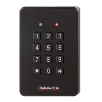
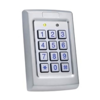
Some readers are not supplied with a cable. Please refer to the reader’s manual for connecting it to the
relevant reader port.
When the AC-825IP is set to Standard mode the address for the reader must be set to 13 and 14. When
the AC-825IP is set to OSDP only the valid addresses can be 1-6.
The OSDP only mode is supported by AxTraxPro only.
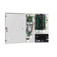
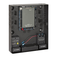
Peripheral devices must be powered up before the AC-825IP.
Refer to the reader specifications for the maximum cable length, typically 150m (492 ft) with an 18 AWG cable.
4. Input and Output Connections
This chapter describes the AC-825IP access control panel's input and output connections.
4.1. Input Types
There are four input types:
•
Normally Closed (N.C.)
•
Normally Open (N.O.)
•
Single EOL resistor
•
Double EOL resistor
Supervised inputs have three states:
•
Normal
•
Abnormal
•
Trouble
The Trouble state is caused by either tampering with the input circuit or by a faulty hardware installation. Once an
input is configured as a supervised input, add a resistor of 2.2 kΩ, 8.2 kΩ, or both on the input circuit. See the
following diagrams.
4.1.1. Normally Open Input Connection
A Normally Open Input has 2 states:
•
Switch Open – Normal State:
Loop resistance = Infinite (open circuit)
•
Switch Closed – Abnormal State:
Loop resistance = 0 (short circuit)
AC-825IP Installation & User Guide
www.rosslaresecurity.com
25
 Loading...