Connectors Description Setup
Inputs
Door1 Request-to-Exit (IN 1A)
Door2 Request-to-Exit (IN 2A)
Door3 Request-to-Exit (IN 3A)
Door4 Request-to-Exit (IN 4A)
Door5 Request-to-Exit (IN 5A)
Door6 Request-to-Exit (IN 6A)
Door7 Request-to-Exit (IN 1C)
Door8 Request-to-Exit (IN 2C)
Door9 Request-to-Exit (IN 3C)
Door10 Request-to-Exit (IN 4C)
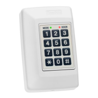
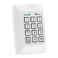
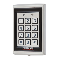
Readers
Reader1 (Door1 IN/OUT)
Reader2 (Door2 OUT /IN)
Reader3 (Door3 IN/OUT)
Reader4 (Door4 OUT /IN)
Reader5 (OSDP) (Door5 IN/OUT)
Reader6 (OSDP) (Door6 OUT /IN)
Reader1D (Door7 IN/OUT)
Reader2D (Door8 OUT /IN)
Reader3D (Door9 OUT /IN)
Reader4D (Door10 OUT /IN)
5.1. R/S/D/P-825 Extension Board DIP Switch Settings
The DIP switches are used when it is necessary to restore the reader to the factory defaults, see Restore to factory
defaults.
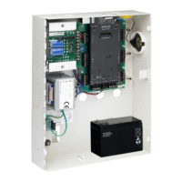
5.2. Setting AC-825IP Panel Type in the AxTraxNG/AxTraxPro Access Control Management
Software
The AC-825IP panel type is defined in the AxTraxNG/AxTraxPro Access Control Management Software. Please refer
to the AxTraxNG User Guide or the AxTraxPro Desktop Client User Guide for further details.
5.3. Configuring OSDP-SC in the AxTraxPro Access Control Management Software
The procedure to configure an AC-825IP for OSDP is given in the AxTraxPro Desktop Client User Guide.
5.4. Restore to factory defaults
1. Turn off power to the controller.
2. Set all the DIP switches to ON.
3. Turn on power to the controller.
4. Wait for three seconds.
AC-825IP Installation & User Guide
www.rosslaresecurity.com
36
 Loading...