6.L7) Drive of
vacuuin
pump
On engines equipped
with vacuum
pump,
check
corresponding
ball- and needle
bearings,
drive
gearand
oil
seal,
andrenew
as
necessary.
SecureAllen
screw
M6x14
withLOCTITEZ2I.On
no
account change
length
of screw.
O NOTE:
Don't
pull
vacuum
pump
apart.
If
need
be, exchange
the complete
unit.
6.18) Ignition
unit:
)*
The
engine is
equipped with
a dual ignition
unit of
a breakerless,
capacitor
discharge
design,
with
an intergrated 250
W
generator.
The
unit consists
of the
generator
stator in
the ignition
cover, the magneto ring
on
the crankshaft, 4
external
trigger coils for ignition,
1
external
trigger
coil
for rev-counter
and
the
ignition
coils
and electronic box in
an
interference
suppression
box
attached on
the aircraft.
Two independent
charging
coils located
on
the
gendrator
stator
supply
one ignition
circuit
each. The energy is
stored
in
capacitors. At
the moment
of ignition
the
two each
external
trigger
coils actuate
the discharge
of the capacitor
to the
primary
circuit
of the
dual ignition
coils. The
operation
of the ignition
unit
is
completely free
of maintenance.
-Sz
U
n*
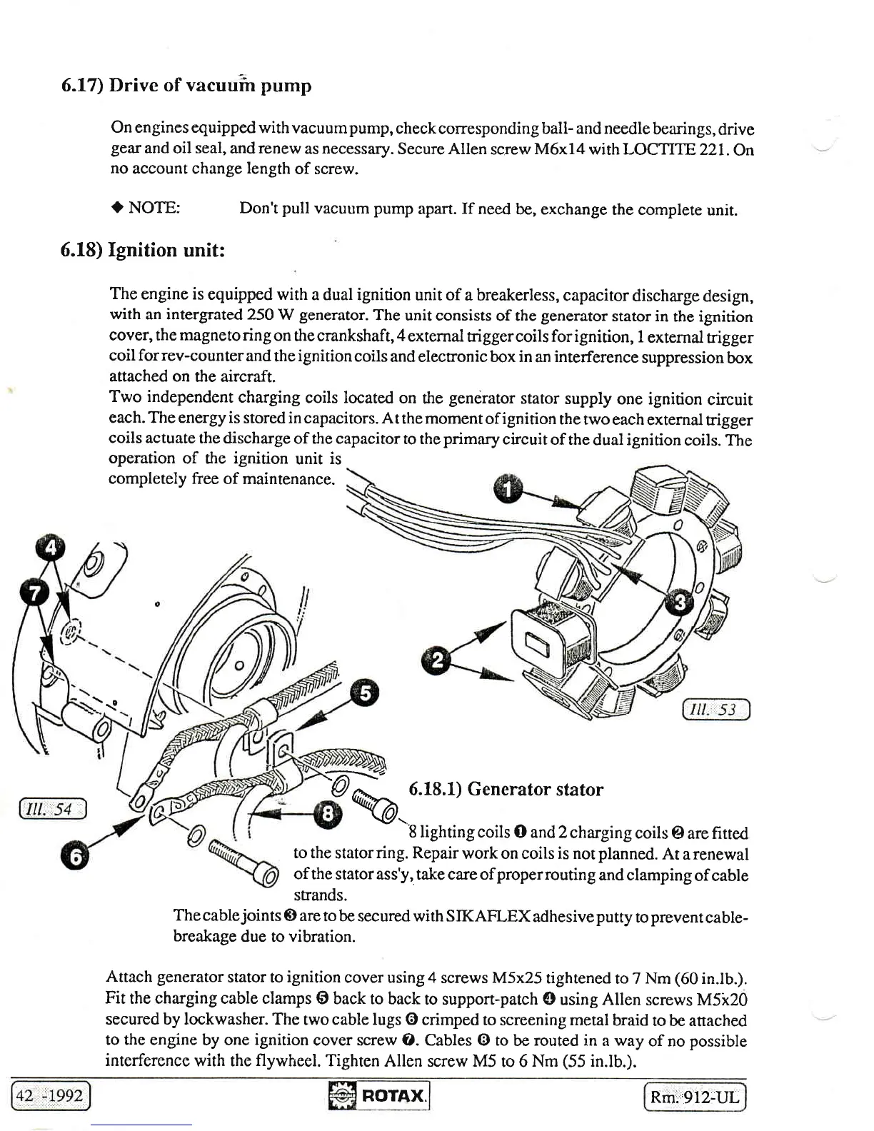
6.18.1) Generator
stator
%r ."''o'r'
\ttrrcr
arul rLarul
8 lighting coils
O and 2
charging
coils
@ arefitred
to the
statorring. Repair
work on coils is not
planned.
At
arenewal
of the
stator ass'y, take care of
properrouting
and clamping
of cable
strands.
Thecablejoints
@ aretobe
securedwith SIKAFLEXadhesiveputty
topreventcable-
breakage
due to vibration.
Attach generator
stator to ignition
cover using 4
screws M5x25
tightened
to 7
Nm
(60
in.lb.).
Fit
the charging cable clamps
@ back to back
to support-patch
@ using Allen
screws M5k20
secured by lockwasher. The
two
cable lugs G)
crimped to
screening metal
braid
to be anached
to the engine
by one
ignition
cover screw O. Cables @ to
be
routed in
a
way
of no
possible
interference
with the
flywheel.
Tighten
Allen screw M5
to 6
Nm
(55
in.lb.).
ROTAX.
Rmi"912-UL

 Loading...


