4 x Set-up and installation
FA ROTEX HPSU compact 4 - 06/2015
17
4.1.3 Scope of delivery
– ROTEX HPSU compact
– Bag of accessories (see fig. 4-3)
4.2 Set-up
Ɣ Remove packing and dispose of it in an environment-friendly
manner.
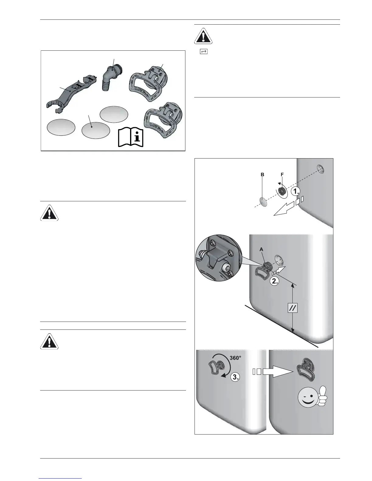
Ɣ Remo
ve the cover plates on the storage tank (fig. 4-4, pos. B)
and unscrew the threaded pieces (fig. 4-4, pos. F) from the
apertures on which the handles are to be mounted (fig. 3-2 to
fig. 3-5, pos. 24).
Ɣ Screw han
dles (fig. 4-4, pos. A) into the threaded holes that
are now free.
A Handles (only required for
transport)
B Cover screen
C Hose connection piece for
safety overflow
D Spanner
Fig. 4-3 Contents of bag of accessories
CAUTION!
Ɣ Onl
y erect the ROTEX HPSU compact when a
sufficient ground load-bearing capacity, of
1050 kg/m² pl
us safety margin, has been assured.
The ground must be flat and level.
Ɣ Outdo
or installation is not permitted.
Ɣ The electronic control system must not be
subjected to atmospheric factors under any
circumstances.
Ɣ The
storage tank must not be exposed to
continuous direct sunlight, as the UV radiation
and the effects of the weather will damage the
plastic.
Ɣ The
ROTEX HPSU compact must be installed in a
manner protected from frost.
Ɣ Make sure that the supply company does not
provide corrosive domestic water.
– Suitable water treatment may be required.
WARNING!
The plastic wall of the storage tank on the ROTEX
H
PSU compact may melt due to the effects of external
heat (>80 °C) and, in the extreme case, can catch fire.
Ɣ Erect the ROTEX HPSU compact only at a
minimum distance of 1 m to other heat sources
(>80 °C) (e.g. electric heater, gas heater, chimney)
and flammabl
e materials.
CAUTION!
If the ROTEX HPSU compact is not erected ade-
quately lower the flat solar panels (the top edge of the
of the storage tank is higher than the bottom edge of
the solar panels), the unpressurised solar system in
the outdoor area will be unable to drain completely.
Ɣ Erect the
ROTEX HPSU compact with a DrainBack
solar connection at a sufficient depth to the flat
solar panels (observe the minimum gradient in the
solar connecting lines).
A Handle
B Cover screen
F Threaded piece
Fig. 4-4 Attach handles

 Loading...

