32
FA ROTEX HPSU compact 4 - 06/2015
4 x Set-up and installation
4.5 Laying coolant lines
Ɣ Check whether oil trap arc necessary.
– Required if ROTEX HPSU compact is not installed at
ground level with the heat pump exterior unit (fig. 4-37,
H
O
10 m).
– At least one oil trap arc must be installed every 10 m dif-
ference in height (fig. 4-37, H = clearance from oil trap arc
to oil trap arc).
– Oil trap arc only required in gas line.
Ɣ Install
lines with bending unit and an adequate clearance to
electrical lines.
Ɣ Only solder with light nitrogen flow
(hard soldering only).
Ɣ Do not app
ly heat insulation to joins until after start-up (for
purposes of leakage search).
Ɣ Establish flange connections and connect to the units.
( Pay attention to the tightening torque, see chapter 10.3
"Tightening torque").
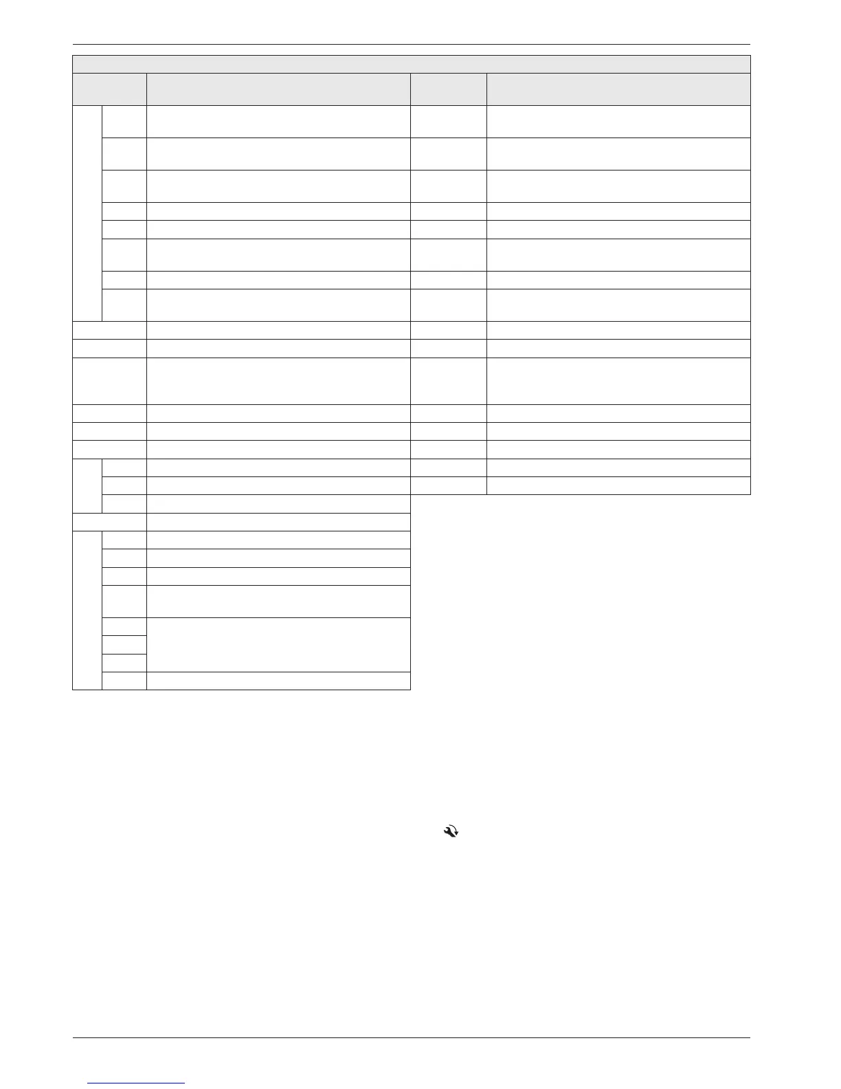
Key names
Short desig-
nation
Explanation Short desig-
nation
Explanation
RoCon BM1
J9 Plug connection FLS (t
R1
/ V1) SG
Switching contact for Smart Grid (intelligent mains
co
nnection)
J10
Plug connection internal cabling
(to A1P)
TRA1 Transformer
J11
Plug connection internal cabling
(to RTX-AL4)
t
AU
External temperature sensor (RoCon OT1)
J12 Plug connection 3UV DHW t
DHW1
Storage tank temperature sensor 1 (RoCon BM1)
J13 Plug connection System-Bus (e.g. room station) t
DHW2
2 (A1P) storage tank temperature sensor
J14 Plug connection circulation pump P
Z
t
R1
Return flow temperature sensor 1 (FLS - RoCon
BM1)
J15 Plug connection internal cabling (strapping plug) t
R2
2 (A1P) return flow temperature sensor
J16
Plug connection room thermostat (RKRTR /
RKRTW)
t
V1
Flow temperature sensor 1 (RTX-AL4)
RoCon M1 Mixer module t
V2
2 (A1P) flow temperature sensor
RoCon U1 Room station t
V, BH
Flow temperature sensor Backup Heater (A1P)
RoCon UFH
Status output for operating mode "Kühlen"
(connection underfloor heating control RoCon
UHF)
V1 Flow sensor (FLS - RoCon BM1)
RT Room thermostat (RKRTW) XAG1 Plug connection exterior heat pump unit
RT-E Receiver for radio room thermostat (RKRTR) XBUH1 Plug connection Backup Heater (BUxx)
RTX-AL4 Switch board (interface) X2M6 Connecting cable clamp HPc-VK-1
RTX-AL4
J1 Plug connection to TRA1 X2M7 Connecting cable clamp HPc-VK-1
J3 Plug connection internal cabling (to A1P) X11M Terminal block in HP convector
J6 Plug connection flow temperature sensor t
V1
RTX-EHS Switch board (Backup heater)
RTX-EHS
K1 Relay 1 for backup heater
K2 Relay 2 for backup heater
K3 Relay 3 for backup heater
X1
Terminal block for mains connection to backup
he
ater
X2_1
Plug connection internal cabling (to XBUH1)X2_2
X2_3
X3 Plug connection internal cabling to J3 (RTX-AL4)
Tab. 4-4 Key names for connections and circuit diagrams - Part 2

 Loading...

