18
FA ROTEX HPSU compact 4 - 06/2015
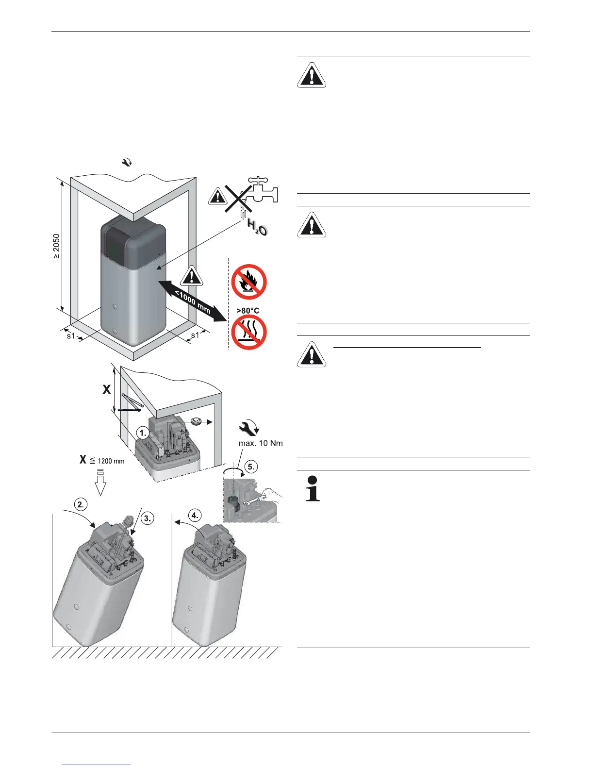
4 x Set-up and installation
Ɣ Install the ROTEX HPSU compact at the installation site.
– Recommended clearances (fig. 4-5):
From the wall (s1): 200 mm.
From the ceiling (X): 12
00 mm, minimum 480 mm.
– Carefully transport the ROTEX HPSU compact, use the
han
dles.
– When setting up the unit in a cabinet, behind panels or in
other restricted conditions, sufficient ventilation (e.g.,
using ventilation gratings) must be ensured.
Ɣ If nece
ssary, install the optional Backup Heater (BUxx) in the
ROTEX HPSU compact (fig. 4-5).
Observe the assembly and operating manual supplied with
the ac
cessory ( for tightening torque see chapter 10.3).
4.3 Water connection
Ɣ For drinking water lines, comply with the EN 806 and DIN
1988 stipulations.
Ɣ To avoid a circulation line, install ROTEX HPSU compact
close to the draw-off location. If a circulation line is absolutely
essential, it must be installed in accordance with the
schematics in chapter 9 "Hydraulic system connection".
Fig. 4-5 Layout (shown on ROTEX HPSU compact 508/516 with incor-
poration of the optional Backup Heater)
CAUTION!
If the ROTEX HPSU compact is connected to a
heating system with steel pipes, radiators or non-dif-
fusion-proof floor heating pipes, slurry and swarf could
enter the hot water storage tank and cause
blockages, local overheating or corrosion.
Ɣ Fl
ush the feed pipes before filling the heat
exchanger.
Ɣ Rinse out the heat distribution network (in the
existing heating system).
Ɣ In
stall the dirt filter or sludge separator into the
heating return flow (see chapter 2.5.5).
CAUTION!
If the ROTEX HPSU compact is connected to a cold
water l
ine, where steel pipes are used, chips can
enter the special steel corrugated pipe heat exchanger
and remain there. This can lead to contact corrosion
damage and subsequently to leakage.
Ɣ Fl
ush the feed pipes before filling the heat
exchanger.
Ɣ In
stall contamination filter in the cold water feed
(see chapter 2.5.5).
ONLY ROTEX HPSU COMPACT ... BIV
CAUTION!
If the h
eat exchanger for charging the pressurised
solar system (fig. 4-1 / fig. 4-2, pos. 8+9) has an ex-
ternal heating unit (e
.g. wood-burning boiler) con-
nected to it, an excessive flow temperature at these
connections can damage or destroy the ROTEX
HPSU compact.
Ɣ Th
e feed flow temperature of the external heater
should be limited to max. 95 °C.
In accordance with EN 12828 you must install a safety
val
ve at or in the immediate vicinity of the heat
exchanger, with which you can limit the maximum per-
missible operating pressure in the heating system.
T
here should be no hydraulic blocking elements
between the heat generator and the safety valve.
Any steam or heating water which may escape must be
diverted by a suitable blow-off line with constant gradi-
ent in a frost-protected, safe and observable manner.
A diaphragm expansion vessel of adequate dimensions
and pr
e-set for the heating system must be connected
to the ROTEX HPSU compact. There should be no
hydraulic blocking elements between the heat genera-
tor and the diaphragm expansion vessel.
ROTEX recommends integrating a mechanical
manometer
for the filling of the heating system.

 Loading...

