8 x Errors, malfunctions and messages
FA ROTEX HPSU compact 4 - 06/2015
45
8 Errors, malfunctions and messages
8.1 Recognising errors, correcting
malfunctions
Electronic control of the ROTEX HPSU compact:
– signals an error by means of the background of the display
ligh
ting up red and shows an error code in the display (see
tab. 8-2).
– shows information messages regarding the operating status,
which
is not signaled by red background lighting.
An integrated Protokoll saves up to
15 error-related or other infor-
mation messages regarding the operating status that last oc-
curred.
Depending on the operating mode, messages are also forwarded
to connected room stations or room thermostats.
8.1.1 Current fault display
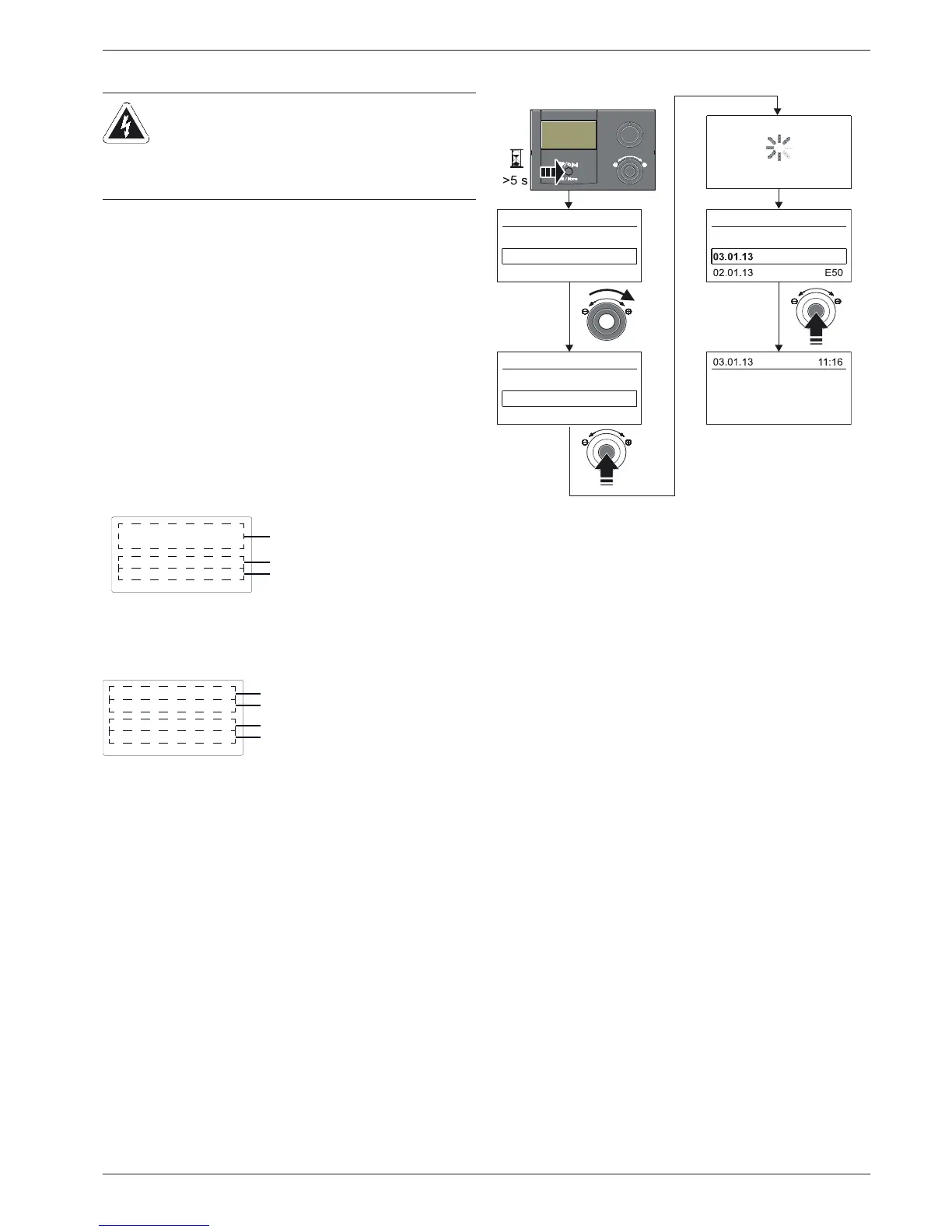
8.1.2 Read Protokoll
The Protokoll can be read in the "Sonderebene" (see fig. 8-3).
The last received (latest) message i
s in the first position. All other
previous messages are then pushed backwards by one place
when a new entry is made. The 15th message will be deleted any
time a new message is received.
8.1.3 Troubleshooting
Information messages, which are displayed without red back-
lighting, normally result in no permanent limitations on the op-
eration of the ROTEX HPSU compact.
Messages that are displayed with an error code E.... and red
back-lighting required error correction by an authorised and
trained expert heating technician.
For information on warning messages see section 8.3.
Ɣ Detecting and remedying the cause of the malfunction.
– Contactor triggered:
Nothing shown on the display in the controller. Ascertain
cau
se of triggering the contactor and remedy fault. Start up
system again.
Î once the cause has been remedied, the system will
resume operations as normal.
– Contactor not triggered:
a) No fault codes are shown but the system is not working
p
roperly. Troubleshooting and eliminating faults (see
section 8.2).
Î Once the cause has been eliminated, the system contin-
ues to work normally.
b) Fault codes are displayed as long as the fault conditions
a
re present. Troubleshooting and eliminating faults (see
Section 8.3). If the fault message is still displayed after the
cause of the fault has been cor
rected, the system must be
disconnected from the power supply for at least 10 in
order to unlock it.
Î Once the cause has been eliminated, the system contin-
ues to work normally.
CAUTION!
Electrostatic charges can lead to voltage arcing that
ca
n destroy the electronic components.
Ɣ Ensure equipotential bonding before touching the
switching field circuit board.
1 Fault message as code (see tab. 8-2)
2 Location information (equipment) of the detected fault
3 Bus address of the unit causing the fault
Fig. 8-1 Displays an active error message (controller fault)
1 Fault message as code (see tab. 8-2)
2 Fault message as clear text (see tab. 8-2)
3 Location information (equipment) of the detected fault
4 Bus address of the unit causing the fault
Fig. 8-2 Display of a current error message (heat pump fault)

 Loading...

