Configuration
Setup
System Configuration
Configuration
System Configuration
HC Configuration
DHW Configuration
HC Configuration
Operating Mode
HC Function
HC Configuration
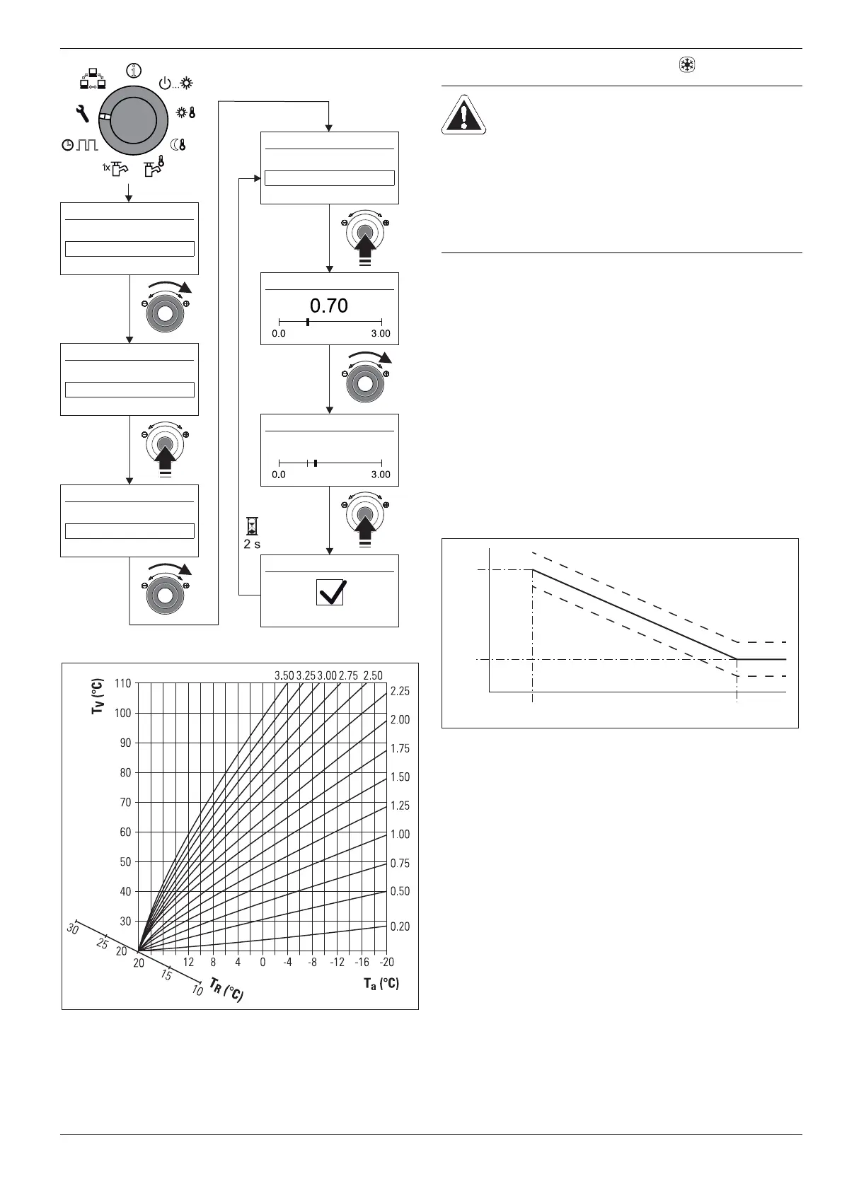
Heat-Slope
Heat Up Opt
Heat-Slope
Heat-Slope
Heat-Slope
Fig. 3-13 Manual setting the heat curve
T
A
External temperature
T
R
Room temperature set value
T
V
Flow temperature
Fig. 3-14 Heat curves
3 x Operation
BA ROTEX HPSU compact 4 - 09/2013
23
More detailed explanations and possible setting values for this function can be seen
in chapter 6.2.
3.6.3 Cooling characteristic curve
Caution - risk of condensation in the screed!
In the event of a fault or wrong setting of parameters,
damage may be caused to the screed, the structure of
the floor and the underfloor heating system by conden-
sation.
● Before initial commissioning, set the maximum
permissible system temperature in the minimum
temperature limit in the Control RoCon HP
(p
arameter [Min T-Flow Cooling]).
With the cooling characteristic curve, the flow temperature is
adjusted to building conditions in a
ccordance with the relevant
outdoor temperature (see section 3.6.2). Warmer outdoor tem-
peratures result in a cold flow temperature and vice versa.
The cooling characteristic curve is adjusted using the following
four parameters:
– [Start T-Out Cooling]
– [Max T-Out Cooling]
– [T-Flow cooling start]
– [T-Flow cooling max]
During the weather-controlled flow temperature regulation, the
user can adj
ust the flow temperature using the parameter
[Cooling Setpoint Adj] by a maximum of 5 °C up or down. The
lowe
r temperature limit is limited by the parameter [Min T-Flow
Cooling].
1 Parameter [Start T-Out Cooling]
2 Parameter [Max T-Out Cooling]
3 Parameter [T-Flow cooling start]
4 Parameter [T-Flow cooling max]
T
A
External temperature
T
V
Flow temperature
Fig. 3-15 Parameter-dependency of characteristic cooling curve
More detailed explanations and possible setting values for this function can be seen
in chapter 6.2.