6 x Parameter settings
BA ROTEX HPSU compact 4 - 09/2013
35
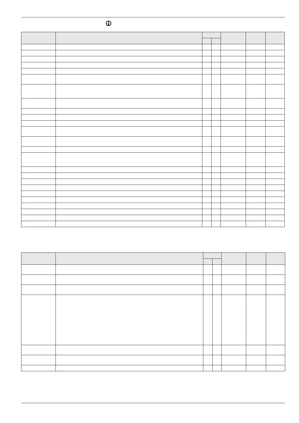
6.10 Rotary switch setting: Info
Parameter Description Access Setting range
Min / Max
Factory
setting
Increment
BE HF
Overview Display of different current operating data. S S - - -
Water Pressure The current water pressure is displayed in bar. S S 0 - 4 bar - 0.1 bar
T-HS The current (flow) temperature of the heat generator is displayed. S S 0 - 100 °C - 1 °C
T-HS Setpoint The current set temperature of the heat generator is displayed in °C with one decimal point. S S 0 - 90 °C - 0.1 °C
T-Outside The current outdoor temperature is displayed in °C with one decimal point. S S -39 - 50 °C 0.1 °C
T-DHW The current temperature of the hot water storage tank is displayed in °C with one decimal point.
If
no hot water function is activated, "- - -" is displayed.
S S 0 - 100 °C - 0.1 °C
T-DHW Setpoint We display the current set temperature for the hot water generation in °C with one decimal
po
int. If no hot water function is activated, "- - -" is displayed. The current set value is here al-
ways the maximum value of all requirements relevant to this hot water circuit.
S S 10 - 70°C - 0.1 °C
T-Return The current return temperature of the heat generator in °C with one decimal point is displayed.
I
f there is no corresponding sensor connected to the heat generator, "- - -" is displayed.
S S 0 - 100 °C - 0.1 °C
Flow Rate The filtered value of the current volume flow is displayed. S S 0 - 5100 l/h - l/h
T-HC The temperature of the direct heating circuit is displayed in °C with one decimal point. S S 0 - 100 °C - 0.1 °C
T-HC Setpoint The set (flow) temperature of the direct heating circuit
is displayed in °C with one decimal point. S S 0 - 900 °C - 0.1 °C
Status HS pump The current status of the internal heat circula
tion pump in the HPSU compact is displayed. S S Off
On
- -
Runtime Compres-
sor
The running time of the compressor is displayed in h. S S - - h
Runtime Pump The running time of the pump is displayed in h. S S - - h
Mixer Position The current direction of flow in the 3-way changeover valve is displayed.
HZ: Room heating
WW: Domestic hot water generation
S S HZ
WW
-
-
Qboh The quantity of heat in the reserve heating for hot water generation is displayed in kWh. S S - - 0.1 kWh
Qchhp The quantity of heat in the reserve heating for heating is displayed in kWh. S S - - 0.1 kWh
Qsc The quantity of heat in the heat pump for cooling is displayed in kWh. S S - - 0.1 kWh
Qch The quantity of heat in the heat pump for heating is displayed in kWh. S S - - 0.1 kWh
QWP The total amount of heat in the heat pump is displayed in kWh. S S - - 0.1 kWh
Qdhw The quantity of heat for hot water generation is displayed in kWh. S S - - 0.1 kWh
HS type The heat generator type HPSU compact detected is displayed. S S - - -
Sw Nr B1/U1 The software and version of the operating unit is displayed. S S - - -
Sw Nr Controller The software number and the version of the regulating board are displayed. S S - - -
Sw Nr RTX RT The software number and the version of the modbus board are displayed. S S - - -
Tab. 6-12 Parameter in rotary switch setting "Info"
6.11 Exit button: Sonderfunktion
Parameter Description Access Setting range
Min / Max
Factory
setting
Increment
BE HF
Manual Operation The internal heating circuit is set constantl
y to an adjustable flow temperature
(see chapter 3.5.1).
E E 20 - 80 °C 50 °C 1 °C
FA failure Display and reset of a current fault from the HPSU compact.
A display of "----" does not indicate a fault (see the control manual).
E E - - -
Error Display and reset of a current fault of the HPSU compact.
A display of "----" does not indicate a fault (see the control manual).
E E - - -
Error Memory Display of fault memory. Here, we display the saved
fault messages of the HPSU compact and
the connected data bus units with date a fault code, in each case as a menu item. By selecting
an entry with the rotary switch, all other corresponding information is displayed concerning the
selected fault message:
- Date and time of the occurrence of the fault
- Fault code (see the control manual).
- Location information (equipment) of the detected fault
- Bus ID of the device causing the fault
With specific faults, the heat demand must be taken back. This
is carried out by actuating the
operating mode [Standby].
There are, however, conditions under which the Con
troller does not accept the fault reset.
E E - - -
Delete massage By setting this parameter to "On" and briefly pressing t
he rotary switch all the entries of the fault
memory, including the faults from connected data bus units are deleted.
E E Off
On
Off -
Timeprog Reset Resets all permanent time programmes to factory setting (see tab. 3-7). E E Off
On
Off -
Return This parameter is used only to exit the special level. E E
Tab. 6-13 Parameter in the level "Sonderfunktion"