3.2
[en] 02/2014
Installation and operating manual - NK 31ROTORCOMP VERDICHTER
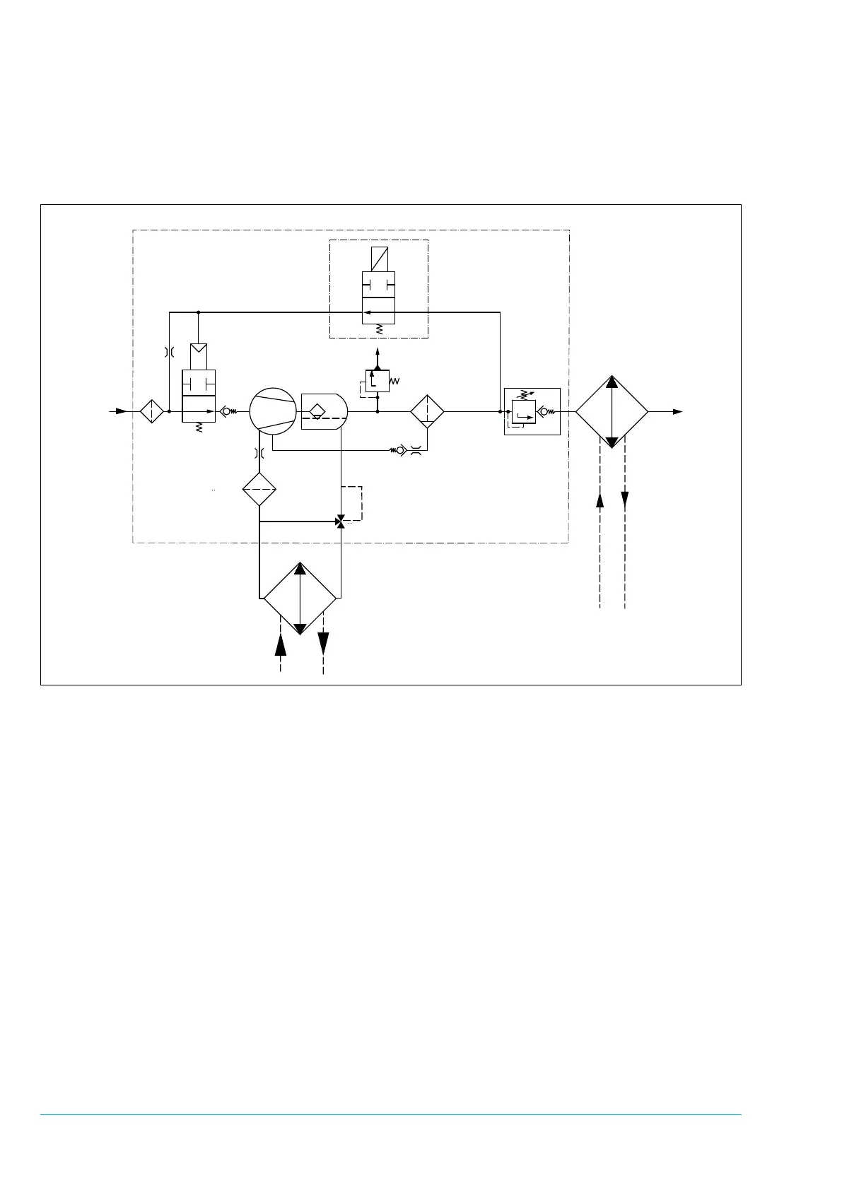
1. Intake lter
2. Intake valve
2.1 No-load nozzle
3. Control unit (electric)
3.1 Solenoid valve
4. Screw compressor
5. Separator tank with pre-separation
6. Fine separator
7. Minimum pressure valve
8. Oil thermostat
9. Oil lter
10. Oil cooler
11. Air after-cooler
12. Non-return valve
13. Safety valve (optional)
Figure 3-2
3.2 Flow diagram of NK 31
(electric control unit)
3.3 Operating description for NK 31
Screw Compressor Compact Module
(electric)
The ow diagram shows a schematic view of the
operating principle and the arrangement of the
main components of the NK 31 screw compres-
sor module with electrical control unit, regardless
of any other equipment.
3.3.1 Standstill
At standstill the solenoid valve 3.1 is deener-
gized, the relief line is open and the downstream
devices are depressurized. The minimum pres-
sure valve 7 set to approx. 5.5 bar at the factory
is tightly closed. The intake valve 2 is slightly
open at standstill.
 Loading...