3.1
[en] 02/2014
Installation and operating manual - NK 31
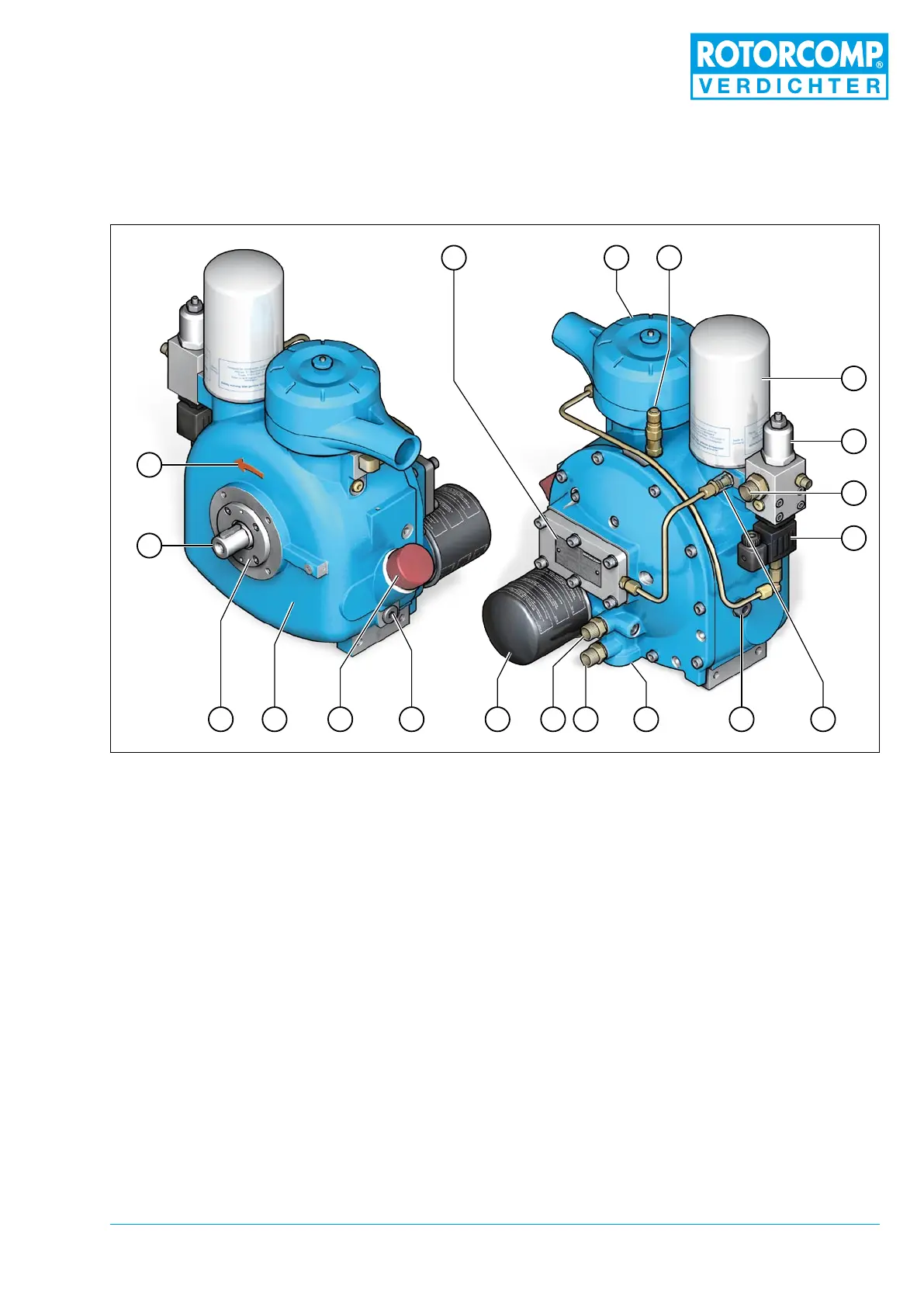
1. Name plate
2. Intake valve with intake lter unit
3. Safety valve (optional)
4. Separator cartridge
5. Minimum pressure valve
6. Compressed air outlet
7. Control block, electric
8. Oil sight glass (optional), oil level control
9. Temperature probe connection
10. Oil-Thermostat
3 Technical Description
4
5
6
7
19
18
12 11
10
8
1617
14
15
13
9
1 32
Figure 3-1
3.1 General overview of NK 31 Screw Compressor Compact Module
(standard model with electric control unit)
11. Oil circuit / outlet
12. Oil circuit / inlet
13. Oil lter
14. Oil drain plug
15. Oil ller
16. NK 31 basic module
17. Front cover
18. Drive shaft
19. Direction of rotation