5.2
[en] 02/2014
Installation and operating manual - NK 31ROTORCOMP VERDICHTER
5.3 Installation
Attention
– The system must be installed at a location at
which the ambient air is as cool and clean as
possible. Never block the air inlet. It must be
ensured that the penetration of moisture with
the intake air is kept to a minimum.
– Screw compressor must always be installed
on a level surface and must be aligned with a
level if necessary.
In exceptional cases, e.g. with mobile systems,
these may only be operated up to a maximum
angle of inclination of 10°.
In these cases the inclined position must be
taken into account when checking the oil level
and must be carried out with particular care.
The base frame for the following fastening ver-
sions must be torsionally rigid and level.
The fastening of the compressor module on a
base frame together with the drive motor can be
designed in accordance with the following ver-
sions.
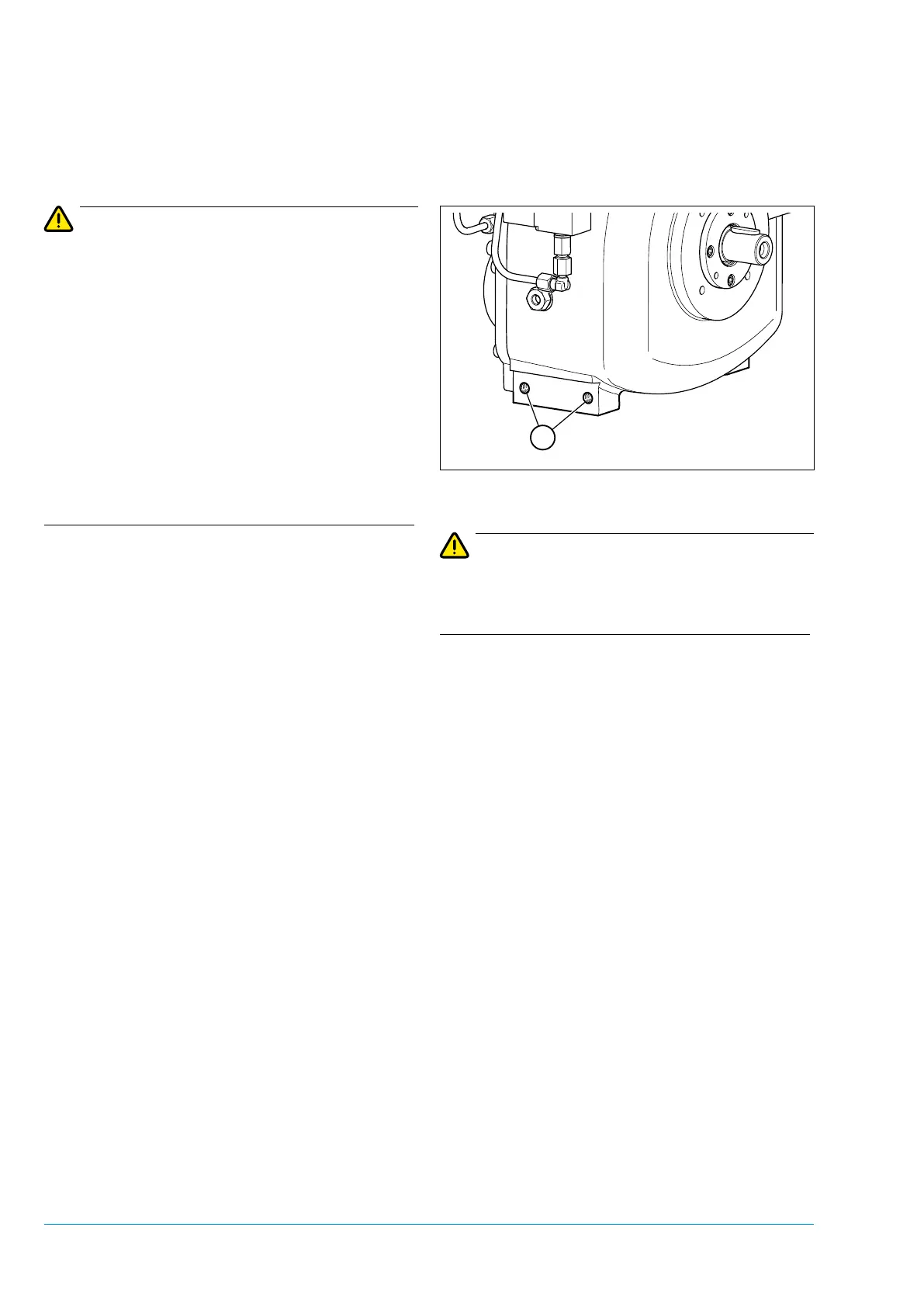
5.3.1 Fastening on base frame with
screw tting
Figure 5-1
Attention
The compressor module may only be fastened at
the side holes on the compressor housing pro-
vided for this purpose.
The unit must be fastened torque-free at the
respective fastening points 1 on the left and right
on the base frame.
5.3.2 Drive
The compressor module is designed as an alter-
native for driving with electric motors, combustion
motors, hydraulic motors, etc.
The power can be transmitted indirectly via a belt
drive (V-belt, toothed belt, etc.) or directly via a
exible coupling.
The direction of rotation, looking at the shaft, is
counterclockwise, i.e. to the left.
On the model with a transmission, the direction of
rotation, looking at the shaft, is clockwise, i.e. to
the right.