3.6
[en] 02/2014
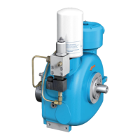
Installation and operating manual - NK 31ROTORCOMP VERDICHTER
3.6.2 Starting
During start-up, the intake valve 2 already opens
at minimum vacuum in the intake chamber of the
screw compressor 4 due to the rotor rotation. The
drawn in air ows via the intake lter 1 through
the intake valve 2 directly into the compression
chamber of the screw compressor 4. There the
intake air is compressed and oil is injected for
lubrication and cooling.
The oil-air mixture then enters the separator
tank 5 in which the majority of the oil is separated
from the air. The air then ows via the ne sepa-
rator 6 and the minimum pressure valve 7 to the
compressed air outlet.
In the ne separator 6 the oil is ltered out down
to a residual content of < 3 mg/m
3
and then
routed back into the compressor housing via a
nozzle and a non-return valve 12.
When the compressor is switched off, the mini-
mum pressure valve 7 with a non-return function
prevents backow of the compressed air out of
the system into the compression chamber in the
discharge phase.
During startup a faster pressure buildup is also
ensured, which is required for optimum lubrica-
tion and oil separation.
When the operating air pressure is reached, the
proportional regulator 3.1 opens and the pilot
air ows under the piston of the intake valve 2,
which begins to close. The adjustable proportion-
al regulator 3.1 steplessly controls the pressure
under the piston of the intake valve 2 in depen-
dence on the compressed-air removal. This pres-
sure acts against the spring force and therefore
determines the valve stroke and the drawn-in
quantity of air.
The compress pilot air ows via the no-load
nozzle 2.1 of the intake valve 2 back into the
compression chamber 4.
The heat resulting during compression is dis-
sipated via the oil-air mixture. The oil circulation
also results from the pressure difference between
the outlet and inlet pressure. The optimum oper-
ating temperature for the oil is adjusted by the oil
thermostat 8. Depending on the oil temperature,
the oil ow is routed directly via the oil cooler
10 or directly to the oil lter 9 by the thermostat
valve.
The oil then ows via the oil lter 9 to the various
injection points in the compressor block.
3.6.3 Switching off
When switching off the system, the intake valve 2
operates, supported by spring pressure, as an in-
dependent non-return valve and closes the intake
opening oil-tight.
 Loading...