3.7
[en] 02/2014
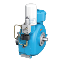
Installation and operating manual - NK 31
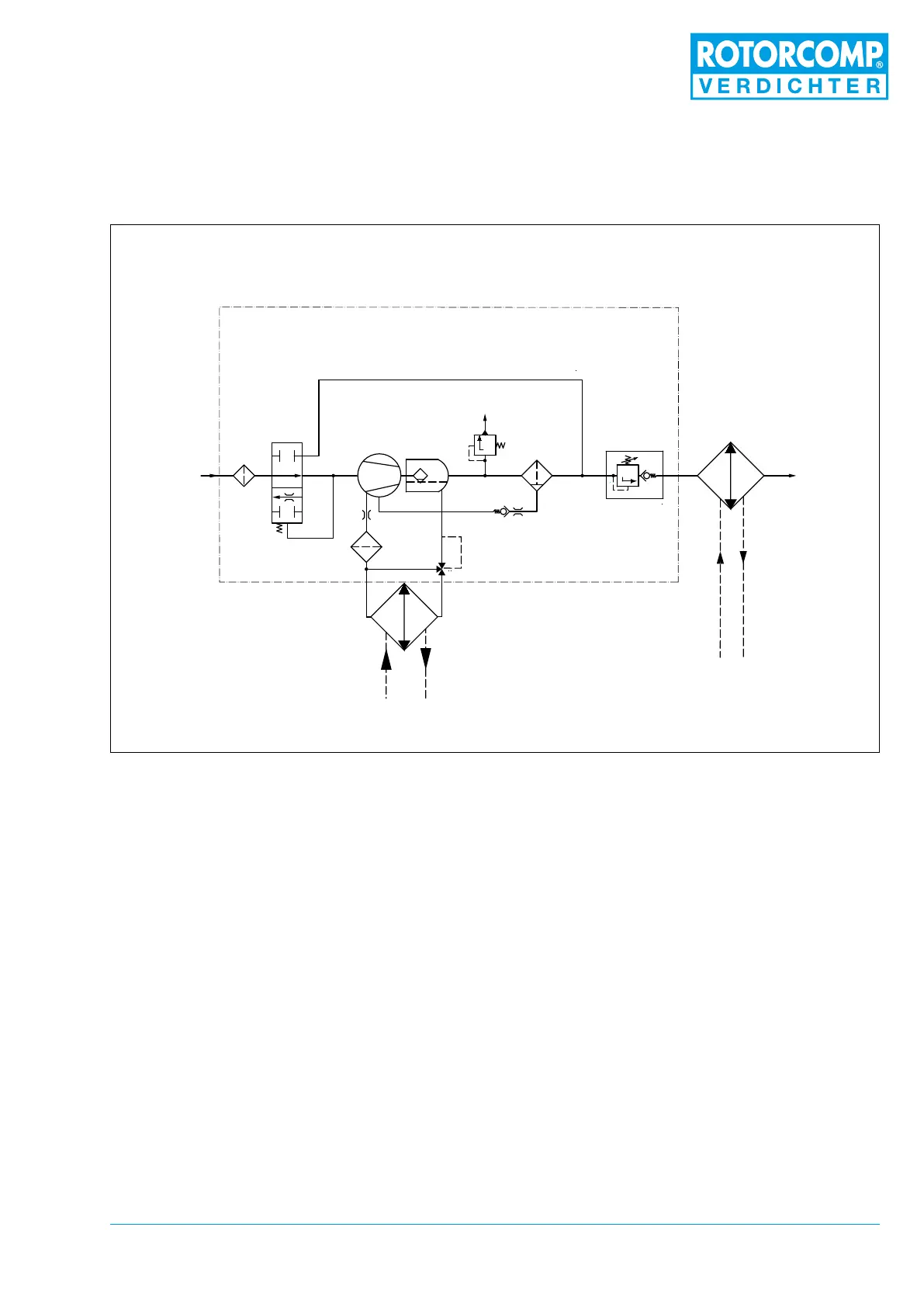
Abbildung 3-5
3.7 Flow diagram of NK 31
(START-STOP controller)
1. Intake lter
2. Intake valve
3. Screw compressor
4. Separator tank with pre-separation
5. Fine separator
6. Minimum pressure valve
7. Oil thermostat
8. Oil lter
9. Oil cooler
10. Air after-cooler
11. Non-return valve
12. Safety valve (optional)
3.8 Operating description for NK 31
Screw Compressor Compact Module
(START-STOP controller)
The ow diagram shows a schematic view of the
operating principle and the arrangement of the
main components of the NK 31 screw compres-
sor module with pneumatic control unit, regard-
less of any other equipment.
In the start-stop controller there is no magnet
control or piston. The start-stop controller func-
tions only mechanically, through the pressure
difference.
3.8.1 Standstill
At standstill the intake valve is slightly open. The
minimum pressure valve 6 is set at 5.5 bar and is
completely closed. The system is depressurized.
 Loading...