3.9
[en] 02/2014
Installation and operating manual - NK 31
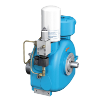
A Intake valve opened
B Intake valve closed
1. Air inlet
2. Air outlet
3. Control line of intake valve
4. No-load/relief nozzle
Figure 3-6
3.9 Intake valve
The NK 31 is equipped with an integrated intake
valve mounted directly on the compressor hous-
ing.
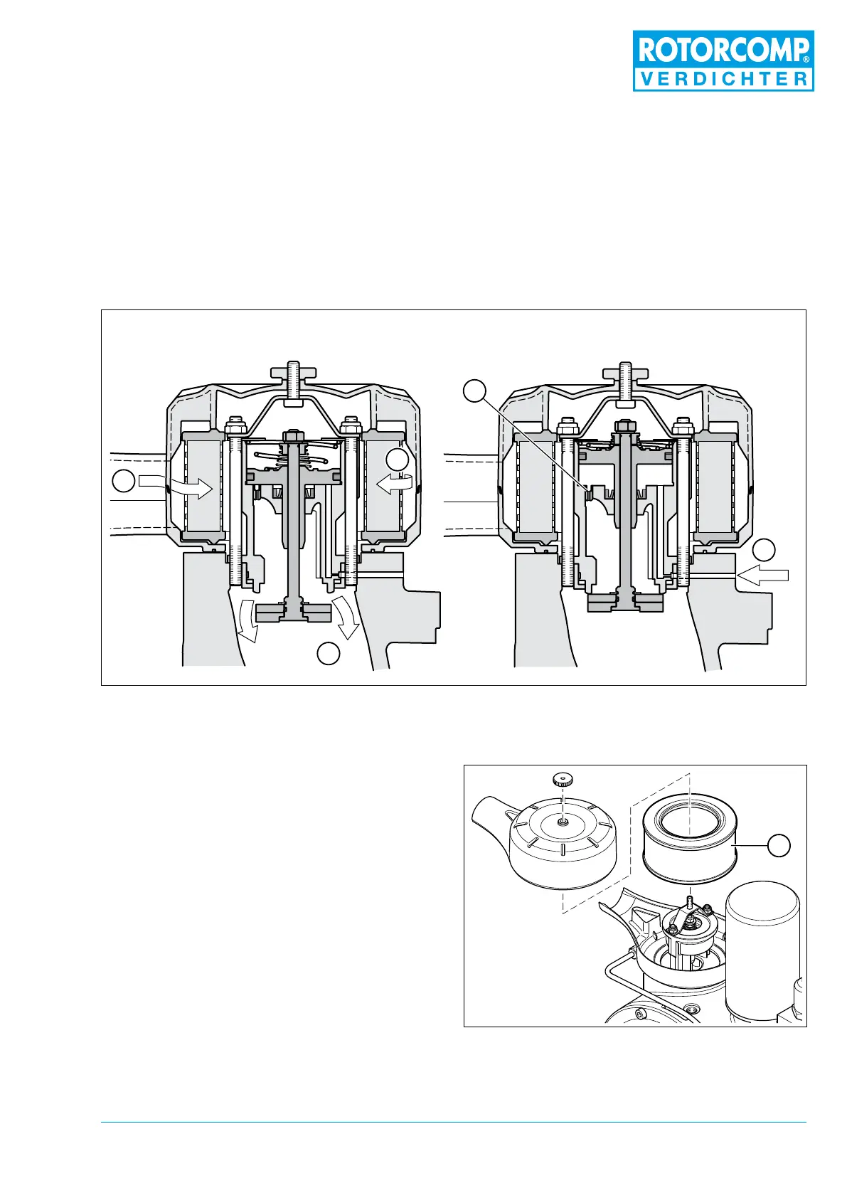
3.9.1 Installation position
Figure 3-7
Different control units can be used for various
operating modes:
– the EMC electric control unit or
– the PMC pneumatic control unit
Depending on the application, various intake
control-valve systems can also be used.