3.15
[en] 02/2014
Installation and operating manual - NK 31
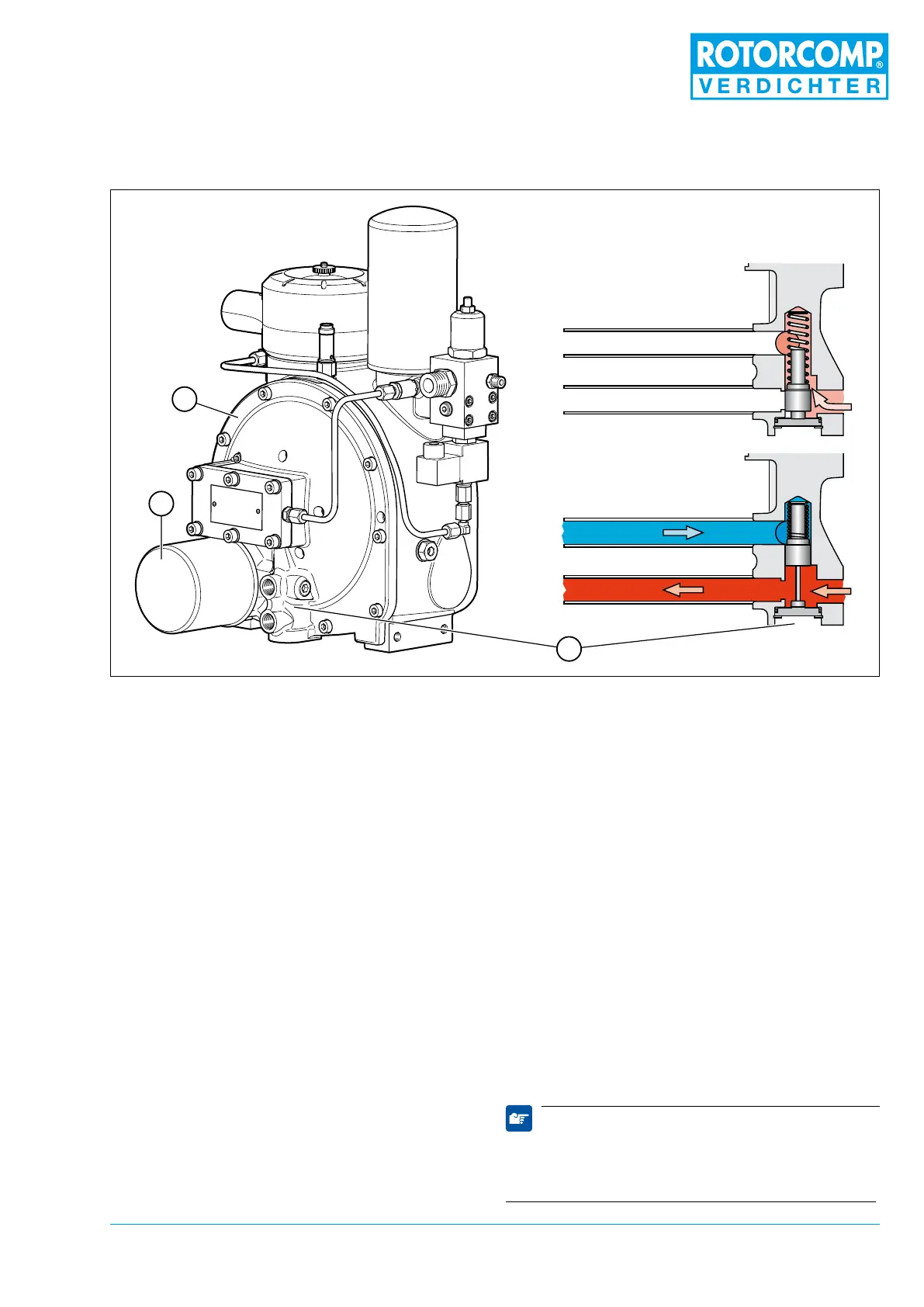
1. Basic module
2. Oil lter
3. Oil thermostat
The oil lter is screwed onto the basic module 1.
The lter neness is 20 μm.
The replacement lter has a bypass valve which
opens with cold, high-viscosity oil or a heavily
soiled lter with a pressure difference of 2.5 bar.
This eliminates the undersupply of the screw
compressor with oil, which results in the maxi-
mum permissible compression temperature being
exceeded.
3.12.2 Oil thermostat
The NK 31 is equipped with an integrated oil
thermostat 3. This is located in the basic mod-
ule 1 before the oil lter 2 and is accessible from
the outside (at bottom).
The oil thermostat working element can be re-
placed and must be selected in accordance with
the operating temperature.
The oil thermostat opens the connection to
the oil cooler when the operating temperature
is reached and controls the maintaining of the
optimum temperature of the system in the fur-
ther process. In the startup phase this parameter
is reached faster, and therefore the formation
of condensate in the oil circulation is largely
avoided. Depending on the compressor operating
data, the temperature is to be between 70°C and
110°C/ 158°F and 230°F (measured at compres-
sor outlet).
When designing the cooling system, the pressure
dew point graph (Figure 8-1) must be taken into
account.
If questions arise concerning the pressure dew
point, please contact ROTORCOMP.
The oil thermostat is maintenance-free. Opera-
tion of the compressor system with an impermis-
sible overtemperature can result in a failure of
the working element (in this case the working
element must be replaced).
Note
When the system is operated at 15 bar, the ther-
mostat working element must always be adapted
to the increased requirements.
3.12.1 Oil lter
Figure 3-14
from radiator
to radiator
3
2
1