A4US
US
A4
US A4
US
A4
A4 US
US
A4
US
A4
A4 US
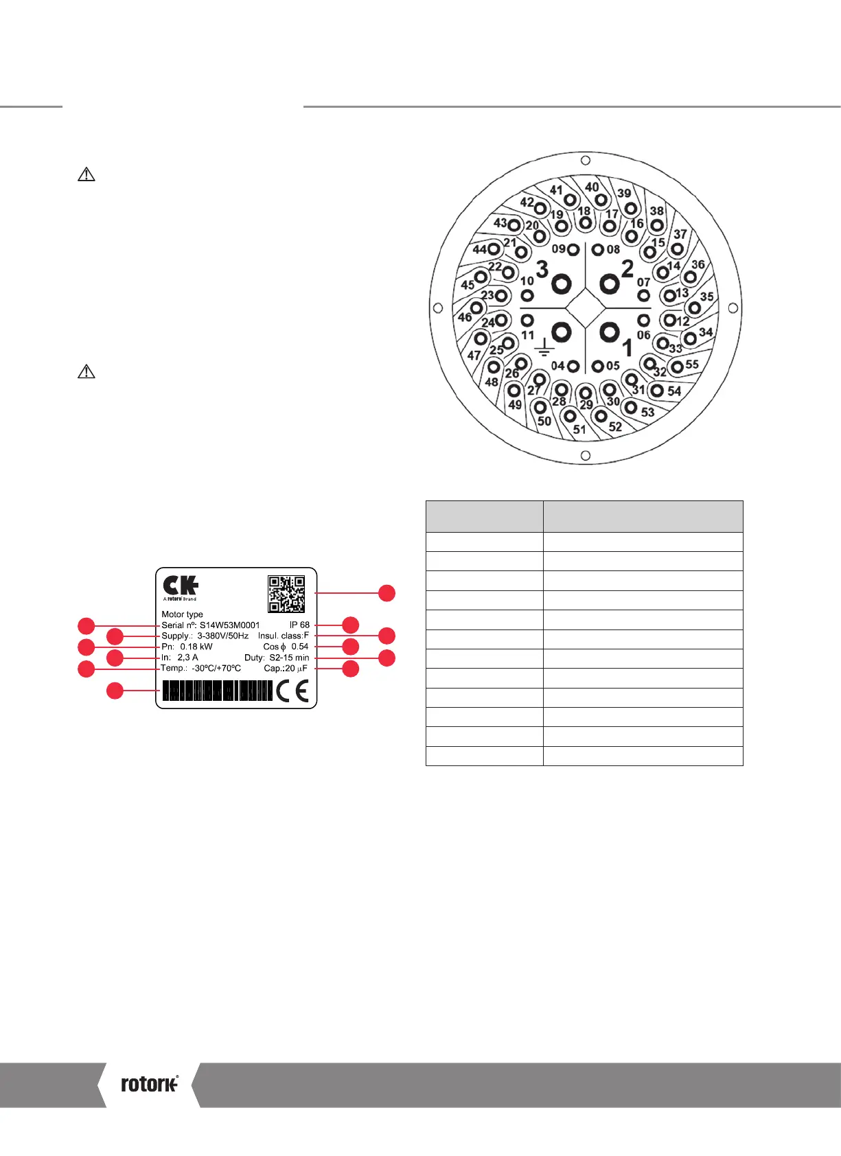
7 Cable Connections
7.1 Terminal block layout
WARNING: Ensure all power supplies are isolated
before removing any covers.
Do NOT run the actuator to limits with incorrect phase
rotation.
Safety Instructions in Section 2 of this document must
be observed and only persons competent by virtue of
their training and experience should carry out electrical
connection.
For unit specific wiring, please refer to the provided
wiring diagram. These can also be downloaded from
www.rotork.com
WARNING: For units including an internal heater.
It is important to isolate the heater supply when heating
is not required.
Electric motor nameplate
The current, mains voltage and mains frequency must match
the data on the motor name plate
:
Mark Description
1 Motor QR Code
2 Enclosure Rating
3 Motor Insulation Class
4 Cos ф Power Factor
5 Duty Rating
6 Capacitor Value
7 Serial Number
8 Supply Voltage
9 Nominal Power
10 Nominal Current
11 Temperature Range
12 Unit Barcode (Factory Use)
10
1
2
3
4
5
11
8
9
7
6
12
CK Range Safe Use and Installation Manual
14