A4US
US
A4
US A4
US
A4
A4 US
US
A4
US
A4
A4 US
A
B
9.5 Basic Mechanical Switch Mechanism
Setting
9.5.1 Instructions
WARNING: Isolate all power to the actuator unless
explicitly instructed otherwise.
Remove the four M6 cap screws retaining the switch
mechanism cover.
Note: Consult wiring to determine specification of switches
fitted.
A 5mm Allen (Hex.) key and 0.8 x 4mm flat screwdriver are
required to perform commissioning of the CK Mechanical
Switch Mechanism.
CAUTION: For CK Standard and CKr actuators,
the required end of travel action (torque or position)
is determined by the set of switches cabled to the
controlling switch gear - refer to actuator terminal plan
and site field wiring.
CAUTION: For CKa, CKra, CKc and CKrc actuators,
the required end of travel action (torque or position) is
determined by settings detailed in Section 9.6.
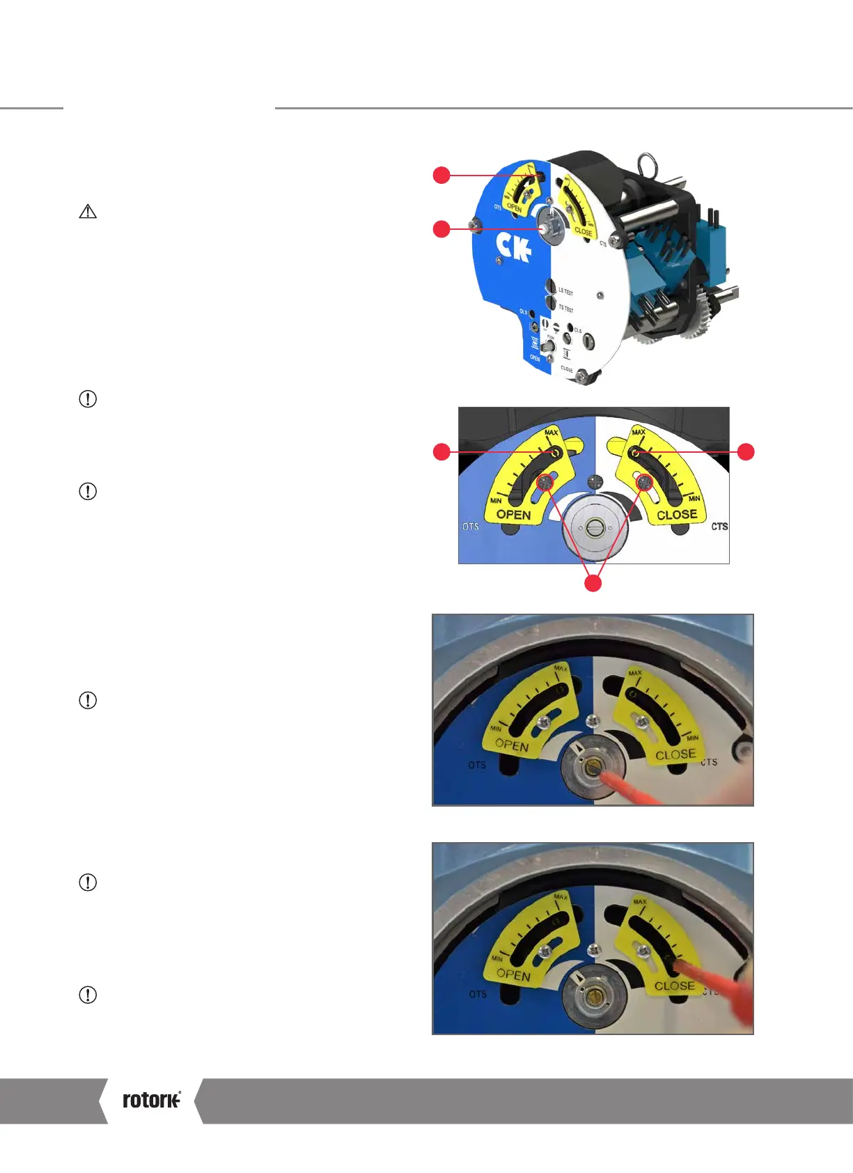
Set Torque Limits
A Indicator/Adjustment Point
B Torque Cam Clutch Screw
C Open Torque Adjustment Point
D Close Torque Adjustment Point
E Factory Calibration Fixings
CAUTION: Do not adjust the factory calibration
fixings or position of the yellow torque indicator plates.
These are factory configured and should not be removed
under anycircumstance.
1) Move the valve to a mid-travel position and loosen the
Torque Cam Clutch 1.5 turns using a flat screwdriver.
2) Adjust each Torque Cam to the desired value - between
min. (40%) & max. (100%) - by moving the cam using a
screwdriver on the adjustment point.
CAUTION: To avoid introducing an offset to the set
value when adjusting the torque trip limits. Ensure
the screwdriver remains perpendicular to the switch
mechanism faceplate.
3) Tighten the Torque Cam Clutch Screw once both torque
trip limits have been set.
CAUTION: Tighten the Torque Cam Clutch Screw until
the spring washer is fully deformed under the screw
head.
C D
E
Torque cam clutch screw adjustment.
Close torque setting adjustment.
9 Commissioning
CK Range Safe Use and Installation Manual
20