A4US
US
A4
US A4
US
A4
A4 US
US
A4
US
A4
A4 US
8) Move the actuator to the valve OPEN position using the
handwheel.
9) Using a flat screwdriver, depress the Drive Clutch Shaft
and rotate to the “Set” position as shown on the switch
mechanism faceplate.
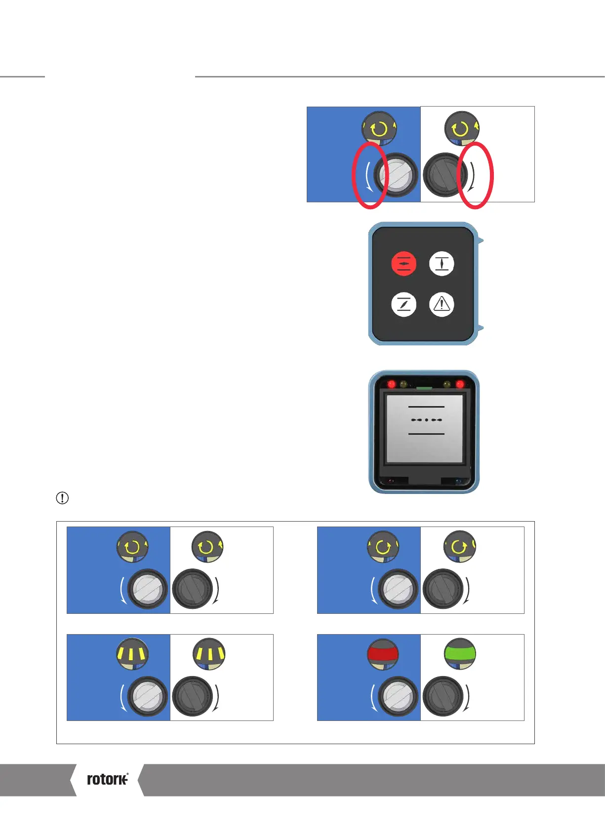
10) The OLS Adjustment Screw must now be rotated to engage
the open limit switch inside the switch mechanism. The OLS
Indicator Window will show one of four possible symbols.
Please refer to Figure 1 below for direction input.
11) Depending on where the mechanism is in the cycle, it is
possible that the switch will be approached from the wrong
direction, in this case it is necessary to move through the limit
and approach it from the correct direction. This avoids the
need to wind through the whole mechanism to reach the
limit position. The correct direction to approach the limit is
shown by the arrow next to the Adjustment Screw input.
12) It is necessary to confirm the switch has engaged correctly.
a. For CK Standard or CK
R
units, measure across the
appropriate terminals using a continuity meter - 16 and 17
for motor control and 18 and 19 for indication feedback.
b.
For CKa or CKra units fitted with an Atronik control module,
confirm the open limit status indicator is illuminated.
c.
For CKc or CKrc units fitted with a Centronik control module,
confirm the position display shows the open limit symbol.
13) Using a flat screwdriver, depress the Drive Clutch Shaft
and rotate to the “Run” position as shown on the switch
mechanism faceplate.
14) Rotate the OLS and CLS Adjustment Screws a small amount
in both directions to re-engage the mechanism drive. A click
will be heard as the drive drops back into engagement and
the adjustment screws will no longer move in either direction.
CAUTION: This must be done or the limit will be lost
when the actuator is moved.
Rotate the OLS/CLS Adjustment Shaft Clockwise. Rotate the OLS/CLS Adjustment Shaft Anti-Clockwise.
Rotate the OLS/CLS Adjustment Shaft in the direction shown
next to the shaft input.
The limit switching point is near or made.
Figure 1.
CLSOLS
CLSOLS CLSOLS
CLSOLS CLSOLS
OPEN LIM
DEMO
Atronik open limit indication.
Centronik open limit indication.
9 Commissioning
CK Range Safe Use and Installation Manual
22
 Loading...


