2 IQ3 manual – Section: Introduction
Table of Contents
1. Introduction _____________________________3
2. Preparing the Drive Bush _________________4
2.1 Thrust Compensators All Sizes ...............4
2.2 Disassembly of bearing assembly:
IQ10 – IQ35 .............................5
2.3 Reassembly:
IQ10 – IQ35 .............................5
2.4 Disassembly of bearing assembly:
IQ40 – IQ95 ............................6
2.5 Reassembly:
IQ40 – IQ95 ............................6
3. Mounting the Actuator __________________7
4. Fitting the Thrust Compensator __________8
4.1 Fitting the Actuator and Thrust Compensator as a
combined Unit: IQ10 – IQ35 .................8
4.2 Fitting Thrust Compensator to Valve Actuator:
IQ40 – IQ95 .............................8
5. Weights _________________________________9
WARNING:
This document must be read in
conjunction with the IQ Instructions for Safe
Use, Installation, Basic Setup and Maintenance
Manual (PUB002-039).
1. Introduction
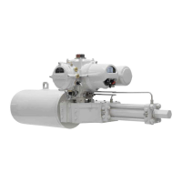
The thrust compensator assembly is designed to
absorb excess thrust being delivered to the valve
structure as the result of stem expansion due to
temperature variation or high speed operation. In
addition, it is designed to maintain sufficient thrust
to retain valve closed position sealing on cooling and
contraction.
CAUTION: Each compensator is individually
configured for the specific, individual valve details
provided. It is therefore mandatory that each
actuator-compensator assembly remains paired
and is fitted only to the intended valve as specified
with the enquiry/order.
Fig. 1.1 Rotork Thrust Compensator
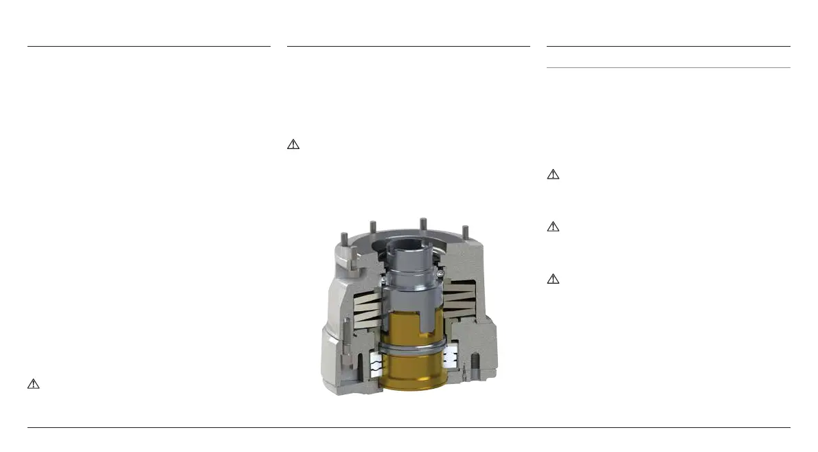
2. Preparing the Drive Bush
2.1 Thrust Compensators All Sizes
Place the thrust compensator with the base plate (2)
facing upwards. Remove the 4 cap-headed screws (1)
holding the base plate (2) in place and remove the base
plate (2) to gain access to the drive bush assembly (3).
Remove the drive bush assembly (3) complete with
its bearing assembly from the thrust compensator
housing. Before machining the drive bush, the bearings
and O-rings must be removed.
WARNING: Do not remove or tamper with
recessed cap-headed screws(*). Adjustment or
removal may result in application failure and/or
injury.
CAUTION: Failure to remove the bearing and
O-rings from the drive bush prior to machining
may result in damage to the bearing or O-ring
components.
WARNING: Component assembly and mass may
present a finger trap hazard.

 Loading...