6 IQ3 manual – Section: Fitting the Thrust Compensator
4. Fitting the Thrust
Compensator
4.1 Fitting the Actuator and Thrust
Compensator as a combined
Unit: IQ10 – IQ35
Fit the machined drive bush into the
thrust compensator as previously
described, lower the actuator onto
the threaded valve stem, engage hand
operation and wind the hand wheel to
engage the drive bush onto the stem.
Continue winding until the actuator
is fully lowered onto the valve flange.
Wind two further turns, fit securing
bolts and tighten fully to the required
torque indicated in PUB002-039 Fig.
6.1.3.
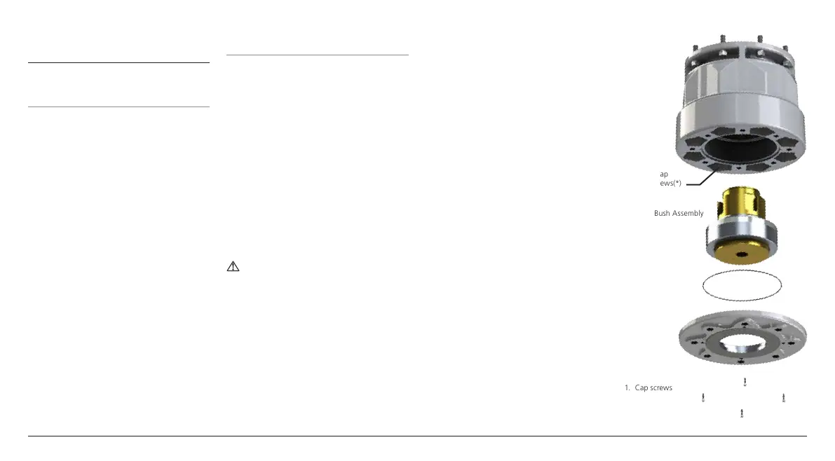
4.2 Fitting Thrust Compensator to
Valve Actuator: IQ40 – IQ95
Fit the loose base plate (2) and drive
bush assembly (3) on to the valve
stem. Lower the thrust compensator
housing onto the valve stem and drive
bush assembly (3). Rotate to align the
drive dogs of the hollow input shaft to
the slots on the machined drive bush
assembly (3). Lower until the thrust
compensator main body is positioned
onto the thrust compensator base
plate (2). Manually rotate the thrust
compensator assembly to align holes
in base plate (2) thrust compensator
housing and valve flange. Fit the
securing bolts and tighten to ensure
the thrust compensator is secure on
the valve flange.
WARNING: Remove lifting
equipment before commencing the
next step.
Fit the mounting studs to the actuator
until hand tight. Lower the actuator
onto the thrust compensator and
rotate until the mounting studs
are aligned with the holes on the
thrust compensator. Engage manual
operation, turn hand wheel until
the drive dogs on the actuator align
with the drive bush of the thrust
compensator. Lower the actuator until
the flange is flush with the thrust
compensator.
Using nuts provided, fix actuator to
thrust compensator and tighten to
required torque, 101 Nm / 74 lbf.ft.
Open the valve by 2 turns and firmly
tighten thrust compensator to the valve
flange. Fixings should be tightened as
per PUB002-039 Fig.6.1.3.
For all other Actuator mounting
instructions please refer to
PUB002-039.
Fig. 4.2.1
Thrust
Compensator
Housing
Recessed cap
headed screws(*)
1. Cap screws
3. Drive Bush Assembly
2. Base plate

 Loading...