IQ3 manual – Section: Preparing the Drive Bush 3
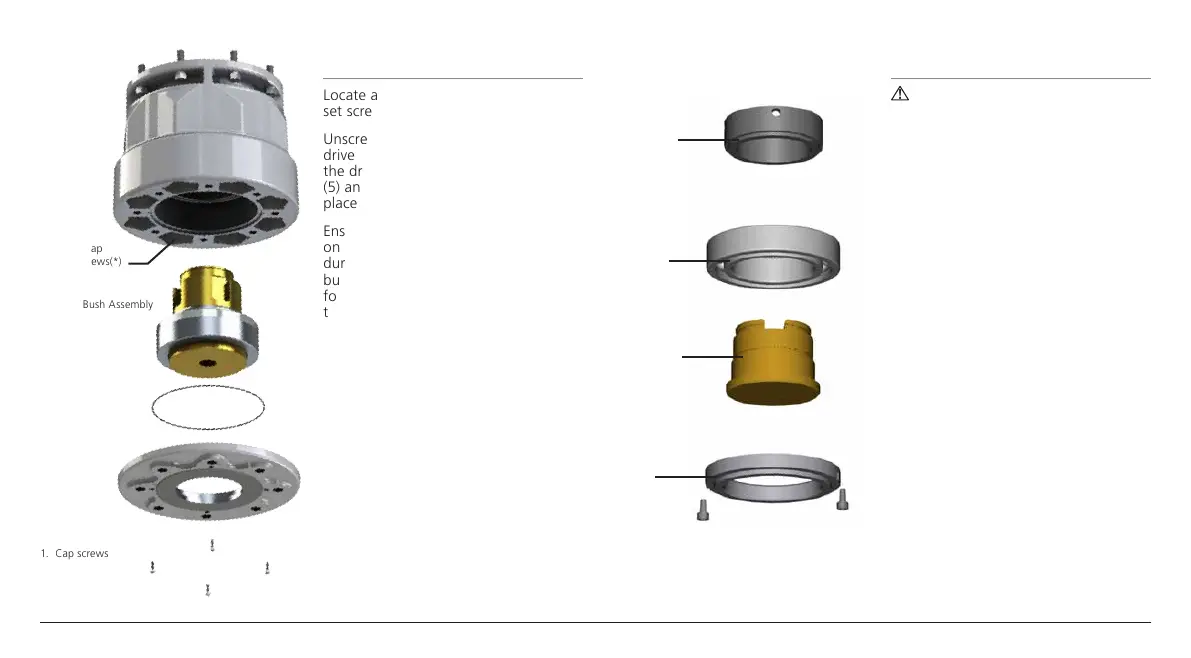
Fig. 2.1.1
2.2 Disassembly of bearing
assembly: IQ10 – IQ35
Locate and loosen the locking socket
set screw in the bearing stop ring (7).
Unscrew the bearing stop ring from the
drive bush (5). Slide the bearing (6) off
the drive bush (5). Keep the drive bush
(5) and stop ring (7) in a safe clean
place.
Ensure the male thread and the O-ring
on the drive bush is not damaged
during machining. Machine the drive
bush (5) to suit the valve stem, allowing
for generous clearance on the screw
thread for rising stem valves.
Fig. 2.2.1
2.3 Reassembly:
IQ10 – IQ35
WARNING: Failure to fully clean
and grease the drive bush and
O-rings before reassembly could
result in damage.
Remove all swarf from the drive bush
(5) ensuring the O-rings on the drive
bush (5) and bearing stop ring (7) are
undamaged, clean and greased.
Slide the bearing assembly (6) onto the
drive bush (5) and ensure it is fitted
down to the drive bush shoulder.
Screw the bearing stop ring (7) with
the locking socket set screw uppermost
on to the drive bush (5) until it is hand
tight. Tighten the locking socket set
screw to lock rotation of the bearing
stop ring (7).
The locking socket set screw must
be sufficiently tight to prevent the
assembly working loose during
operation. Refer to the following table
for correct tightening information.
continued over...
Thrust
Compensator
Housing
Recessed cap
headed screws(*)
1. Cap screws
3. Drive Bush Assembly
2. Base plate
7. Bearing
Stop Ring
6. Sealed Thrust
Bearing
5. Drive Bush
4. Retaining
Plate

 Loading...