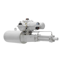
4 IQ3 manual – Section: Preparing the Drive Bush
Locking Socket
Screw Size
Torque
Nm lbf.ft
M4 2.2 1.62
M6 7. 8 5.75
Grease and refit the drive bush
assembly (3) into the thrust
compensator housing ensuring that the
slots on the drive bush (3) are located
into the drive dogs of the hollow input
shaft inside the thrust compensator
housing.
Refit the base plate (2) and secure with
cap-headed screws (1). Tighten M6
cap-headed base retaining screws (1) to
11 Nm / 8 lbf.ft.
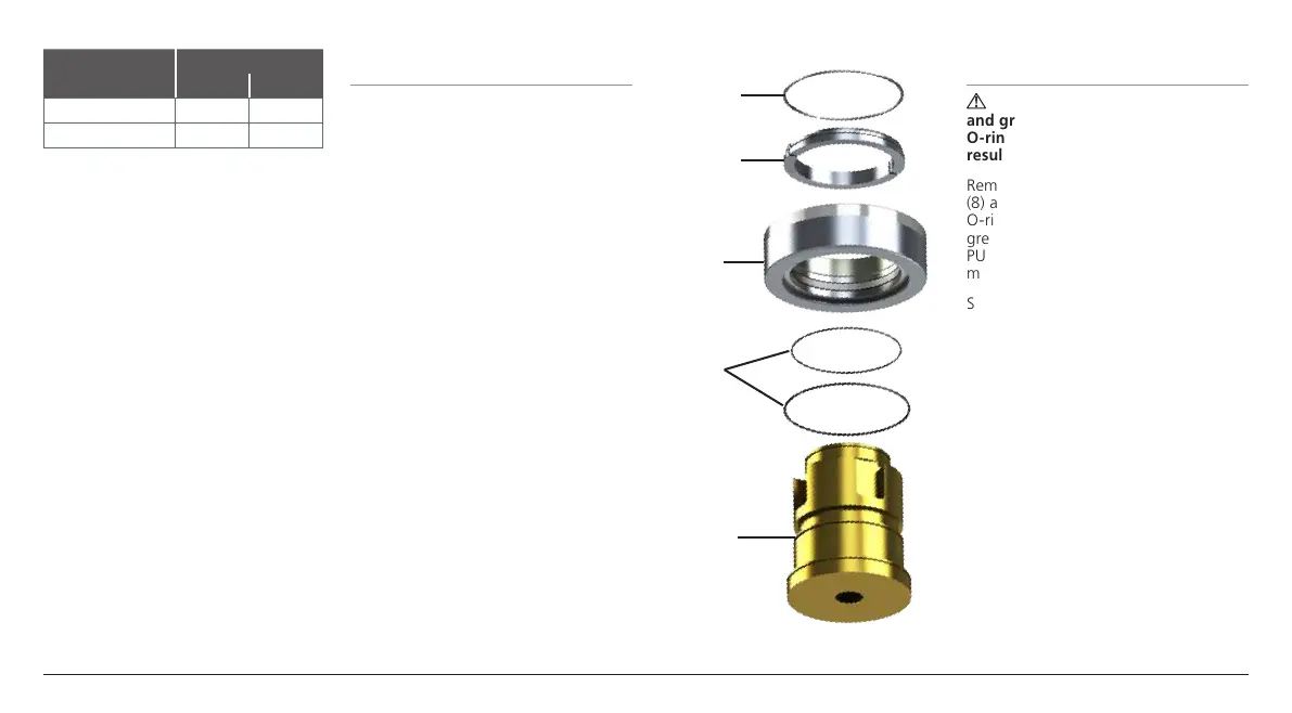
2.4 Disassembly of bearing
assembly: IQ40 – IQ95
Locate and remove the snap ring (12)
using a suitable tool. Remove the split
collar (11). Slide the thrust bearng (10)
and O-rings (9) off the drive bush (8).
Keep the bearing, O-rings and drive
bush locating components in a safe
clean place. The split collar (11) must be
kept as a matched pair.
Machine the drive bush (8) to suit
the valve stem, allowing a generous
clearance on the screw thread.
Fig. 2.4.1
2.5 Reassembly:
IQ40 – IQ95
WARNING: Failure to fully clean
and grease the drive bush and
O-rings before reassembly could
result in damage.
Remove all swarf from the drive bush
(8) and refit O-rings, ensuring all
O-rings are undamaged, clean and
greased (for typical greases refer to
PUB002-039 Section 11, weights and
measures).
Slide the thrust bearing (10) onto the
drive bush and ensure it is fitted down
to the drive bush shoulder. Grease and
refit matched pair split collar (11) and
snap ring (12).
Grease and refit the drive bush
assembly (3) into the thrust
compensator housing ensuring that the
slots on the drive bush (3) are located
into the drive dogs of the hollow input
shaft inside the thrust compensator
housing.
Refit the base plate (2) and secure with
cap-headed screws (1). Tighten M6
cap-headed base retaining screws (1) to
11 Nm / 8 lbf.ft.
12. Snap Ring
11. Split Collar
10. Thrust
Bearing
9. O-rings
8. Drive Bush

 Loading...