IN-E-HyFlex-V4_10
Rotronic AG
Bassersdorf, Switzerland
Document code Unit
Instruction Manual
Document Type
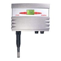
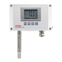
HygroFlex transmitter version 4: instruction
manual
Document title
Page 17 of 61
© 2006; Rotronic AG IN-E-HyFlex-V2_10.doc
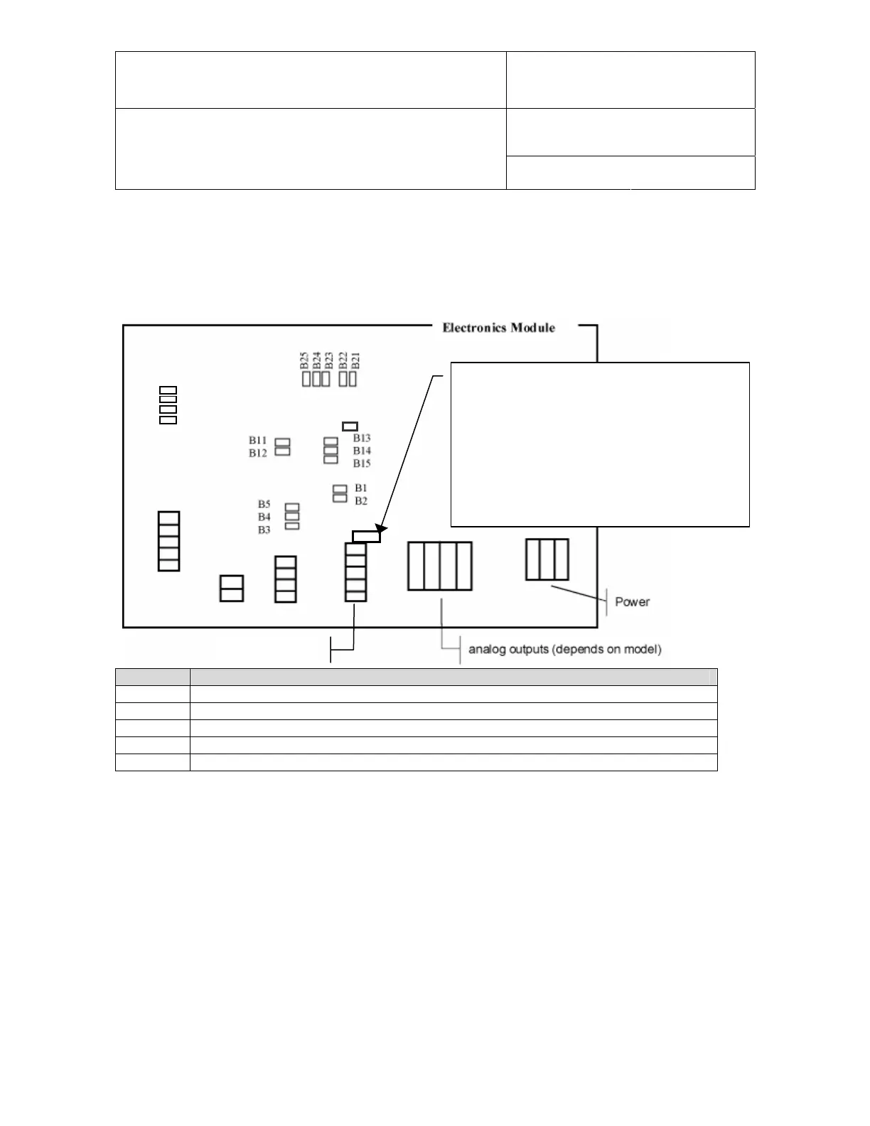
4.7 Analog signal configuration (HygroFlex 1 and 3 main PCB)
On the HygroFlex 1 and HygroFlex 3, the type of analog output signal can be selected by means
of jumpers on the PCB:
HygroFlex 1: to configure the temperature range
and unit, use this 3-pin service connector and
connect to a PC with cable # AC1623.
HygroFlex 3: the transmitter can be configured
by connecting the RS232 / RS485 output to a
PC.
For both transmitters, configuration requires the
HW4 software installed on the PC.
RS232 / RS485
B31
B32
B33
Res.
B34
Signal Jumpers to be closed
0…1 V B2, B3, B12, B13, B22, B23, B31
0…5 V B2, B4, B12, B14, B22, B24, B32
0…10 V B2, B5, B12, B15, B22, B25, B31, B32
0…20mA B1, B3, B11, B13, B21, B23, B33, B34
4…20mA B1, B3, B11, B13, B21, B23, B31, B33, B34
The scale of each analog output can be changed with the HW4 software (see separate
instructions). On the HygroFlex 3, the parameter corresponding to the third output can also be
changed by software (see software instructions).